
This information has been submitted by Alan (aka bigtrailbikerider)
***ALWAYS DISCONNECT THE MOTORCYCLES BATTERY BEFORE COMMENCING ANY ELECTRICAL INSTALATION***
Autoswitch Wiring:
Red – Green/blue wire inside the fuse-box (only live when ignition is switched on).
Purple – Relay Terminal No 86. (Relay Control wire, once indicator cancel switch has been depressed longer than 0.8 sec sends supply to relay).
Black – Relay Terminal No 85 (Earth, then a Piggy-back connector to Brown wire inside the fuse-box.)
Black Twin Core – Pre-wired Bi coloured LED (Secured in place by the self adhesive cable tie base).
Orange – Brown/white wire inside the fuse box. (Trigger sensor wire from indicator signal button).
Relay Wiring:
Relay Terminal No 85 – Earth.
Relay Terminal No 86 – Relay Control from Autoswitch.
Relay Terminal No 87 – Supply feed to the auxiliary lights.
Relay Terminal No 30 – Main (10a) fused feed from the battery.
Fitting Procedure:
. Remove the seats and fuel tank. Fitment can be done quite successfully without the removal of the fuel tank, though it is more awkward.
. Disconnect the battery.
. Remove the four screws that secure the top of the fuse box, two on either side.
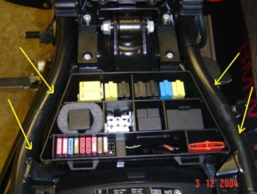
. Remove the top of the fuse box. This is a tight fit between the two frames rails; slowly flex the lid so that removal can be made easier. Warming the lid with a heat gun is strongly recommended as it allows the plastic lid to flex more and greatly assists in its removal.
ABOVE ALL………. “DO NOT TRY AND FORCE IT OUT!”
. Care should be taken not to subject any of the wires underneath to any undue strain.
. Once the fusebox is clear of the frame, remove the large rubber grommet that is situated at the front of the fuse box that supports the main loom as it enters into it.

. There are two sealed slots in the grommet, carefully cut out both the slots and the centre of the holes.

. Replace the grommet and slide the two power cables though one of the slots. One is the main feed from battery; the other is the feed to the lights. The LED wire goes through the other slot.
. Identify which of the motorcycles wiring needs to be connected to the Autoswitch/Relay: -
o Brown – Black (Relay/Autoswitch)
o Brown/white – Orange (Autoswitch)
o Green/blue – Red (Autoswitch)
. Using the high adhesive taped backing provided in the kit, secure the Autoswitch inside the fuse box.
. Connect the Autoswitch control wires to the appropriate wires inside the fuse box.
. The simplest way to connect to these wires is by utilizing the Scotchloc connectors that are provided within the kit. They are fine and are very quick and easy to use.
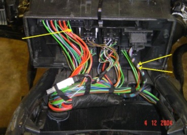
. But it should be noted as they make small indentations into the wires as they cut into the insulation; over a period of time this “could” result in a poor connection. It is therefore recommended that the joint is done by splicing back the insulation and soldering the feed wire to it, as per the photograph shown below.
. The soldered joint should then covered with insulation tape or better still heat shrink to avoid a possible short circuit to earth.

. Feed all the power wires and the wires from the Autoswitch through the vacant socket in the left hand side of the fusebox.
. Replace the top part of the fusebox, again taking great care to avoid possible damage.
. Warming the lid again with a heat gun is strongly recommended as it allows the plastic lid to flex more and greatly assists in it being manipulated back in-between the frame rails.
ABOVE ALL……….”DO NOT TRY TO FORCE IT BACK IN!”
. Connect all the wires to appropriate relay connections, see Autoswitch & Relay wiring paragraphs on the first page.
. The relay is held in place by the foam provided. Simply place the foam around the relay and gently push it into the spare aperture.

. Carefully route both the LED and the feed wire to the lights up along the frame and under the tank (if not removed) to the front of the bike. Extreme care are should be taken in the routing of these cables to avoid possible chaffing and the possibility of a potential short circuit to earth.
. It would aid the installation if the headlight assembly were also removed.
. The LED is held in place under the dashboard, using the self-adhesive cable tie base provided.

. Connect the positive wire from each of the lights to the feed wire from the Autoswitch
. Connect the negative wires (earth) from each light to a suitable earth point. Personally I utilize the M8 Allen bolt that is situated just under the ignition barrel for all the earths.

But most importantly of all……………TAKE YOUR TIME!!!!!
Cheers,
Alan (aka bigtrailbikerider)
DISCLAMER
Whilst every effort has been made to ensure the accuracy of this document, the author or UKGSer can not be held responsible for damage, injury, loss or expense resulting from errors or omissions.
***ALWAYS DISCONNECT THE MOTORCYCLES BATTERY BEFORE COMMENCING ANY ELECTRICAL INSTALATION***
Autoswitch Wiring:
Red – Green/blue wire inside the fuse-box (only live when ignition is switched on).
Purple – Relay Terminal No 86. (Relay Control wire, once indicator cancel switch has been depressed longer than 0.8 sec sends supply to relay).
Black – Relay Terminal No 85 (Earth, then a Piggy-back connector to Brown wire inside the fuse-box.)
Black Twin Core – Pre-wired Bi coloured LED (Secured in place by the self adhesive cable tie base).
Orange – Brown/white wire inside the fuse box. (Trigger sensor wire from indicator signal button).
Relay Wiring:
Relay Terminal No 85 – Earth.
Relay Terminal No 86 – Relay Control from Autoswitch.
Relay Terminal No 87 – Supply feed to the auxiliary lights.
Relay Terminal No 30 – Main (10a) fused feed from the battery.
Fitting Procedure:
. Remove the seats and fuel tank. Fitment can be done quite successfully without the removal of the fuel tank, though it is more awkward.
. Disconnect the battery.
. Remove the four screws that secure the top of the fuse box, two on either side.
. Remove the top of the fuse box. This is a tight fit between the two frames rails; slowly flex the lid so that removal can be made easier. Warming the lid with a heat gun is strongly recommended as it allows the plastic lid to flex more and greatly assists in its removal.
ABOVE ALL………. “DO NOT TRY AND FORCE IT OUT!”
. Care should be taken not to subject any of the wires underneath to any undue strain.
. Once the fusebox is clear of the frame, remove the large rubber grommet that is situated at the front of the fuse box that supports the main loom as it enters into it.
. There are two sealed slots in the grommet, carefully cut out both the slots and the centre of the holes.
. Replace the grommet and slide the two power cables though one of the slots. One is the main feed from battery; the other is the feed to the lights. The LED wire goes through the other slot.
. Identify which of the motorcycles wiring needs to be connected to the Autoswitch/Relay: -
o Brown – Black (Relay/Autoswitch)
o Brown/white – Orange (Autoswitch)
o Green/blue – Red (Autoswitch)
. Using the high adhesive taped backing provided in the kit, secure the Autoswitch inside the fuse box.
. Connect the Autoswitch control wires to the appropriate wires inside the fuse box.
. The simplest way to connect to these wires is by utilizing the Scotchloc connectors that are provided within the kit. They are fine and are very quick and easy to use.
. But it should be noted as they make small indentations into the wires as they cut into the insulation; over a period of time this “could” result in a poor connection. It is therefore recommended that the joint is done by splicing back the insulation and soldering the feed wire to it, as per the photograph shown below.
. The soldered joint should then covered with insulation tape or better still heat shrink to avoid a possible short circuit to earth.
. Feed all the power wires and the wires from the Autoswitch through the vacant socket in the left hand side of the fusebox.
. Replace the top part of the fusebox, again taking great care to avoid possible damage.
. Warming the lid again with a heat gun is strongly recommended as it allows the plastic lid to flex more and greatly assists in it being manipulated back in-between the frame rails.
ABOVE ALL……….”DO NOT TRY TO FORCE IT BACK IN!”
. Connect all the wires to appropriate relay connections, see Autoswitch & Relay wiring paragraphs on the first page.
. The relay is held in place by the foam provided. Simply place the foam around the relay and gently push it into the spare aperture.
. Carefully route both the LED and the feed wire to the lights up along the frame and under the tank (if not removed) to the front of the bike. Extreme care are should be taken in the routing of these cables to avoid possible chaffing and the possibility of a potential short circuit to earth.
. It would aid the installation if the headlight assembly were also removed.
. The LED is held in place under the dashboard, using the self-adhesive cable tie base provided.
. Connect the positive wire from each of the lights to the feed wire from the Autoswitch
. Connect the negative wires (earth) from each light to a suitable earth point. Personally I utilize the M8 Allen bolt that is situated just under the ignition barrel for all the earths.
But most importantly of all……………TAKE YOUR TIME!!!!!
Cheers,
Alan (aka bigtrailbikerider)
DISCLAMER
Whilst every effort has been made to ensure the accuracy of this document, the author or UKGSer can not be held responsible for damage, injury, loss or expense resulting from errors or omissions.


