
Many GSers have installed Malky's excellent Widetail units in the rear indicators. The LED units offer both high reliability and give more presence to the bike. Unfortunately, the Widetails no longer appear to be available. However, the following can be applied to both the front and rear indicators.
By adopting Malky's Widetail idea, I have installed a similar setup on the front of my R1150GS. If you can use a soldering iron and join a few wires, then this is a DIY exercise. Here's how:
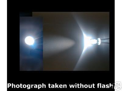
Firstly, you'll need to go shopping for some LEDs. White for the front, red for the rear! If you can get 12v super-bright LEDs, they would be best. However, most LEDs require a lower voltage. I used 5 each side of these 5mm white 10,000 - 14,000 mCd brightness LEDs...
For white LEDs you can use Farnell part 9870423. As these are 3.4v LEDs, you need to wire each in series with a 560 ohm resistor such as Farnell's 9339590
If your bike bike has yellow indicator lenses, you'll also need to buy a pair of white lenses (BMW part No 63 13 7 658 957) and a pair of orange indicator bulbs.
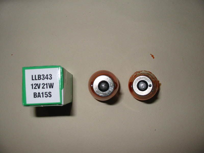
It is unlikely that you will get the bulbs from your dealer - or even Halfords - as most orange bulbs have offset pins and, if your bike had orange lenses, you will need 180 degree pins. The picture below shows the difference. You need the LLB343 bulb. I bought mine from a corner motorist shop at £1 each.
Remove the indicator lenses (each retained by one crosshead screw) and prise out the silver plastic reflector. Carefully remove the two wires noting which goes to which terminal (brown is earth on my bike). Remove the bulb.
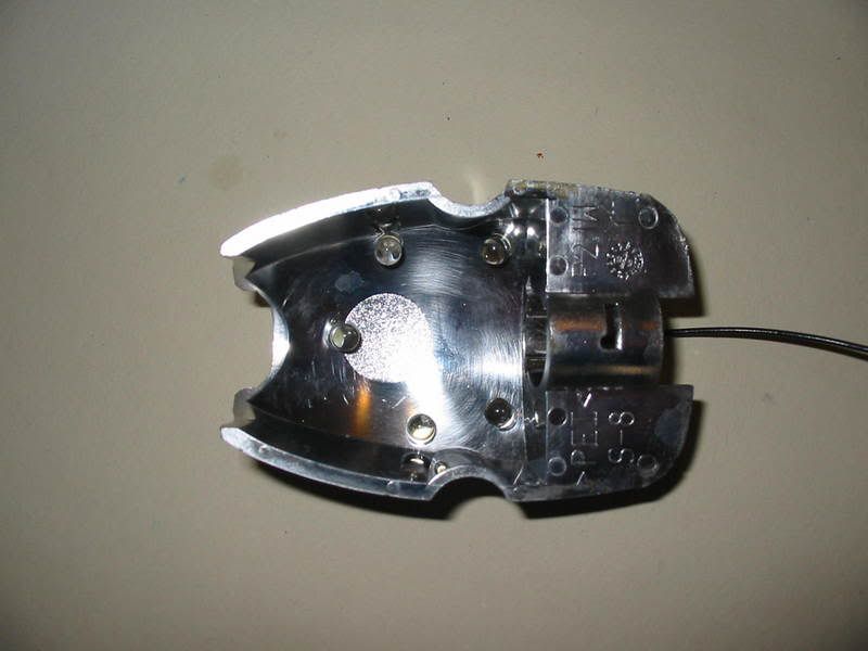
From the rear, carefully drill five x 5mm holes around the circumference of the reflector. Insert and glue with epoxy resin (Araldite Rapide) the five LEDs, ensuring that the longer wires of the LEDs (the anodes, which will be connected to the +ve power supply) are all similarly orientated. From the inside, it should now look like this:
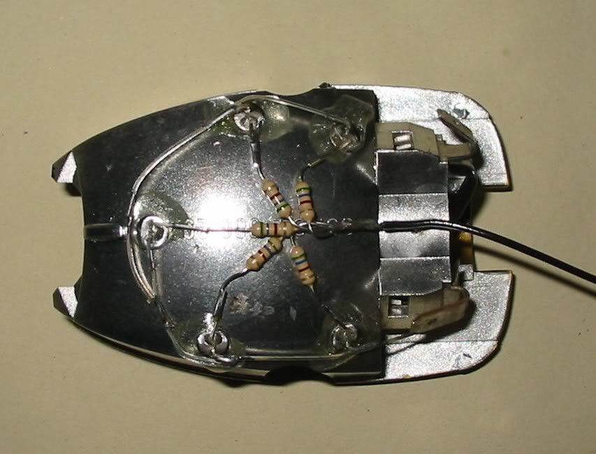
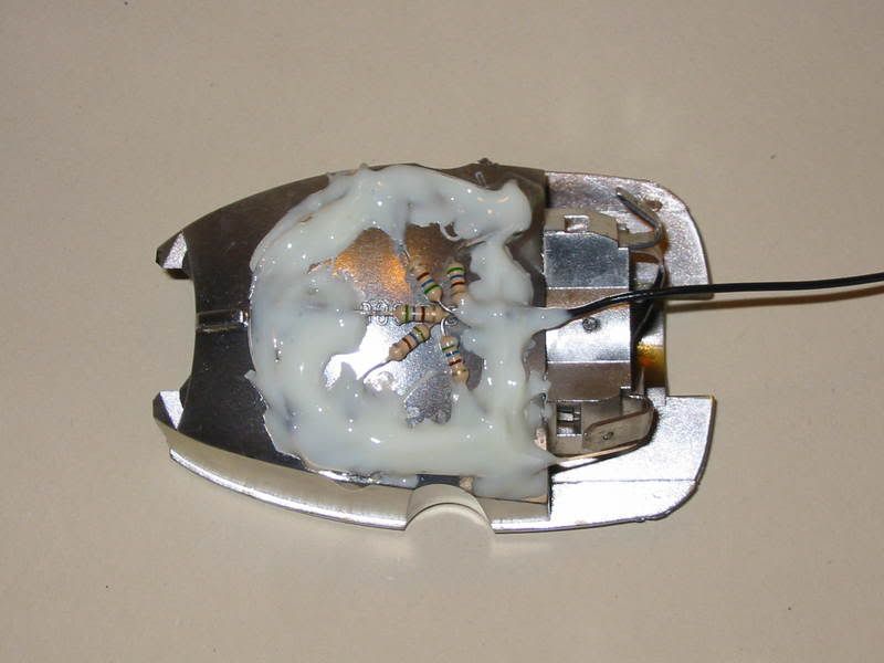
Now comes the part that will test your soldering skills! The LEDs are designed to operate at 3.4v, not the 13-14v that your bike operates at. So each LED must be wired in series with one of the 560 ohm resistors. Solder each resistor (either way round) to the longer terminal (anode) of each LED. Join the loose ends of the resistors and solder a supply wire (the total power consumption of these 5 LEDs is about 1 watt, so very light cable will suffice). Then solder the shorter LED wire (cathode) of the LED closest to the earthing tag, and then solder the cathodes of the other LEDs to each other ensuring that they do not touch the anodes. It should look something like this:
Stablise the wiring, the resistors and the LEDs with more epoxy resin. However, don't use too much as the unit still has to fit its mounting!
When the epoxy has set, insert the orange bulb and remount the unit on the bike, ensuring that you reconnect the indicator feed and earth wires to the same terminals from which they were removed.
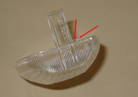
If you are modifying your bike from orange lenses to white lenses, you need to cut off this oblong tag with a junior hacksaw.
Reinstall the reflector and lens on the bike, pushing the wire through the hollow mounting arm.
Thread your two new wires through the existing cable ties as you route the cables to the parking light in the main beam unit. Connect the wires to the 'live' side of the parking lamp feed using a piggy-back spade terminal (or similar). If you select the wrong parking lamp wire, your new lights won't work but no damage will be done. Simply reconnect to the other wire.
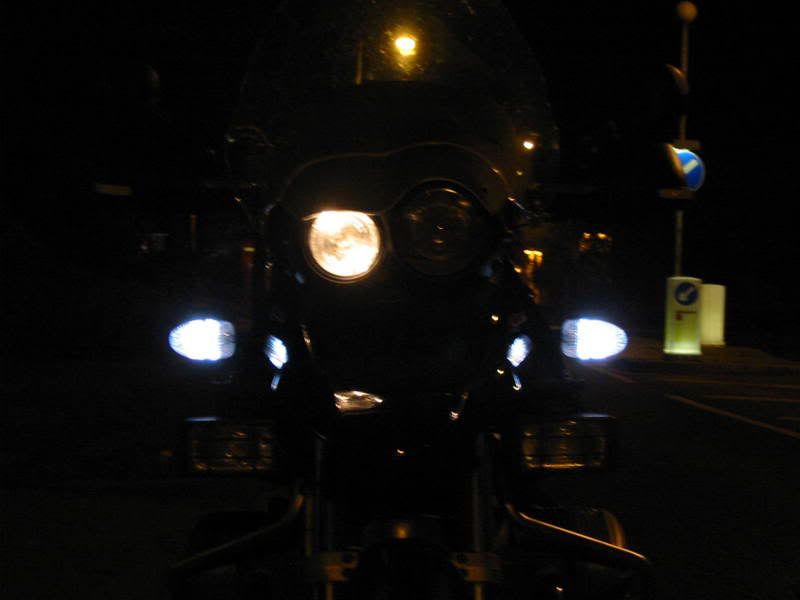
The indicators still flash orange and the finished result looks like this:
By adopting Malky's Widetail idea, I have installed a similar setup on the front of my R1150GS. If you can use a soldering iron and join a few wires, then this is a DIY exercise. Here's how:
Firstly, you'll need to go shopping for some LEDs. White for the front, red for the rear! If you can get 12v super-bright LEDs, they would be best. However, most LEDs require a lower voltage. I used 5 each side of these 5mm white 10,000 - 14,000 mCd brightness LEDs...
For white LEDs you can use Farnell part 9870423. As these are 3.4v LEDs, you need to wire each in series with a 560 ohm resistor such as Farnell's 9339590
If your bike bike has yellow indicator lenses, you'll also need to buy a pair of white lenses (BMW part No 63 13 7 658 957) and a pair of orange indicator bulbs.
It is unlikely that you will get the bulbs from your dealer - or even Halfords - as most orange bulbs have offset pins and, if your bike had orange lenses, you will need 180 degree pins. The picture below shows the difference. You need the LLB343 bulb. I bought mine from a corner motorist shop at £1 each.
Remove the indicator lenses (each retained by one crosshead screw) and prise out the silver plastic reflector. Carefully remove the two wires noting which goes to which terminal (brown is earth on my bike). Remove the bulb.
From the rear, carefully drill five x 5mm holes around the circumference of the reflector. Insert and glue with epoxy resin (Araldite Rapide) the five LEDs, ensuring that the longer wires of the LEDs (the anodes, which will be connected to the +ve power supply) are all similarly orientated. From the inside, it should now look like this:
Now comes the part that will test your soldering skills! The LEDs are designed to operate at 3.4v, not the 13-14v that your bike operates at. So each LED must be wired in series with one of the 560 ohm resistors. Solder each resistor (either way round) to the longer terminal (anode) of each LED. Join the loose ends of the resistors and solder a supply wire (the total power consumption of these 5 LEDs is about 1 watt, so very light cable will suffice). Then solder the shorter LED wire (cathode) of the LED closest to the earthing tag, and then solder the cathodes of the other LEDs to each other ensuring that they do not touch the anodes. It should look something like this:
Stablise the wiring, the resistors and the LEDs with more epoxy resin. However, don't use too much as the unit still has to fit its mounting!
When the epoxy has set, insert the orange bulb and remount the unit on the bike, ensuring that you reconnect the indicator feed and earth wires to the same terminals from which they were removed.
If you are modifying your bike from orange lenses to white lenses, you need to cut off this oblong tag with a junior hacksaw.
Reinstall the reflector and lens on the bike, pushing the wire through the hollow mounting arm.
Thread your two new wires through the existing cable ties as you route the cables to the parking light in the main beam unit. Connect the wires to the 'live' side of the parking lamp feed using a piggy-back spade terminal (or similar). If you select the wrong parking lamp wire, your new lights won't work but no damage will be done. Simply reconnect to the other wire.
The indicators still flash orange and the finished result looks like this:
Last edited:


