Top Dead Centre Tool - 2017 R1200GS Adventure

Done mine this morning. Both sides were a smidgeon out of alignment so I corrected them for the practice.
I had to use a small 1/4” drive socket to apply enough torque to the chain tensior because of my arthritic hands but apart from that it was fairly straightforward.
I note my TDC tool isn’t marked A / B on the ends and I’m ashamed to say I used the 6mm end for the first cylinder so had to do it again :blast

Well done for having a go though, I'll be doing mine fairly soon.

Just waiting for SnapOn to send me the 16mm Torque Adapter ring
 
Ahem, I said on Friday night, not "on a Friday night". :p

Friday's the night after tomorrow night, assuming today's still Wednesday?
 
Hi Boxflyer,
Thanks for all your time and effort on this issue. Can I ask you to clarify the alignment of the ignition device on the lhs?
I watched and rewatched that section of your video and have aligned the mark on the device (I guess it’s a magnet ring) with the bottom edge of the end diameter of the sensor.
Is that correct please?

This part isn't clear on anything I've seen so far. So a detailed clean answer would be very useful.
 
This part isn't clear on anything I've seen so far. So a detailed clean answer would be very useful.

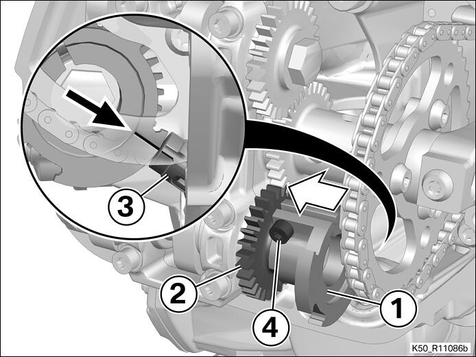
Perhaps this picture, courtesy BMW RepDVD, may help to clarify.


46761442904_d78b11471f_b.jpg


Description:
-- Install trigger (1) and push it all the way on to camshaft (2).
-- Align trigger (1) with the mark (arrow) pointing to the groove in camshaft sensor (3).
-- Tighten screw (4) 6Nm
 
Hi Boxflyer,
Thanks for all your time and effort on this issue. Can I ask you to clarify the alignment of the ignition device on the lhs?
I watched and rewatched that section of your video and have aligned the mark on the device (I guess it’s a magnet ring) with the bottom edge of the end diameter of the sensor.
Is that correct please?

Shakey...
The screen shot from kuntk is exactly correct.
The only amplification I can add is that there are 2 arrows in the picture and the instructions below the image from the RepROM aren't too clear.

The white arrow is indicating to slide the trigger all the way on the camshaft and the inset circular picture shows the alignment mark correctly positioned reference the lower edge of the notched cutout on the cam sensor pickup.

Good work kunth!
 
Knutk - many thanks. That clarifies it for me.

Boxflyer - thanks again. I’m going to double check anyway before I go ahead and refill the oil.
 
Seems a lot of faffin about, does the cam timing go out of spec?
What causes that, is it chain wear?
 
It’s possible as there’s no key or splines to index the sprockets on the cam shafts. I beleive that this has been the source of some exhaust header severe over heating so it’s worth chemcking during a 12,000 mile service.
 
Good post alignment run out today. More deep burble, less rattle.

To be honest (and I’m no expert) I really do wonder whether the tiny adjustment needed will have much effect on the time the cam nose exerts maximum thrust on the valve but I do perceive a change in the running compared to pre-check
 
Good post alignment run out today. More deep burble, less rattle.

To be honest (and I’m no expert) I really do wonder whether the tiny adjustment needed will have much effect on the time the cam nose exerts maximum thrust on the valve but I do perceive a change in the running compared to pre-check

Very good, need to do mine soon :)
 
Good post alignment run out today. More deep burble, less rattle.

To be honest (and I’m no expert) I really do wonder whether the tiny adjustment needed will have much effect on the time the cam nose exerts maximum thrust on the valve but I do perceive a change in the running compared to pre-check

Hyperdrive or warp speed achieved Martin.............:beerjug:
 
A end is 8mm diameter
B end is 6mm diameter

There are only 2 slots on the alternator rotor exterior...both are 8mm wide to accept the A end...
You can put the B end in the 8mm slot, but it will have play/slop and the timing check will be all over the place.
 
A end is 8mm diameter
B end is 6mm diameter

There are only 2 slots on the alternator rotor exterior...both are 8mm wide to accept the A end...
You can put the B end in the 8mm slot, but it will have play/slop and the timing check will be all over the place.

That's what I said :D
 
A end is 8mm diameter
B end is 6mm diameter

There are only 2 slots on the alternator rotor exterior...both are 8mm wide to accept the A end...
You can put the B end in the 8mm slot, but it will have play/slop and the timing check will be all over the place.

:thumb:thumb:thumb You are so helpful, everything is really appreciated.


Back
Top Bottom