finally fixed my rear light!

russ996duke

Well-known member
UKGSer Subscriber
Joined
May 25, 2004
Messages
2,251
Reaction score
166
Location
Cardiff, Wales
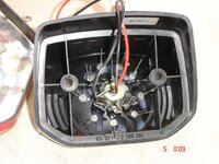
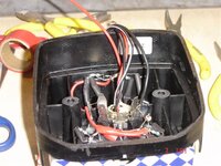
My old GS1100 goes well, but the rear light unit is definetly showing its age, works only when it "feels" like it....so decided to try and fix it...so I took it off to have a look:thedummy

all the contacts "gone" and even the reflective coating on the plastic reflector
turned to dust!

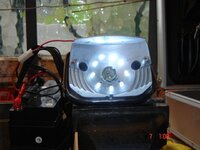
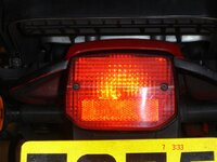
So, taking a leaf out of Greg Masters book on converting turn signals into running lights, a few LEDs bought and I now have both standard rear stop and tail AND an LED rear light, which should mean that even if the bulb blows, I still have a rear light!:thumb2

And all it cost me was a bit of time when it was too hot to ride anyway!

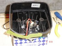
First had to replace the knackered bulb holder, so out with the drill and all that crap removed and a new bulb holder glued into place
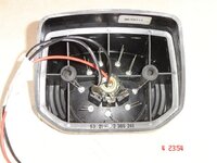
Second, out with a can of spray paint in anice shade of aluminium and reflector is as good as new:augie
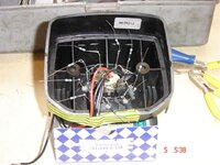
Then drill holes for the 5mm leds, glue 'em in and wire them up with resistors
(www.ultraleds.co.uk)
the connect them into the wiring for the replacement bulb holder and Robert is your Fathers brother!
I will try to post piccys, wish me luck!
 

Attachments

  • rearledconversion006.jpg
    rearledconversion006.jpg
    59.8 KB · Views: 202
and here is another piccy
(and I do so look forward to the comments on my lack of abilities as a sparky!
 

Attachments

  • rearledconversion013.jpg
    rearledconversion013.jpg
    77.3 KB · Views: 167
and the proof that the leds do work!
 

Attachments

  • rearledconversion014.jpg
    rearledconversion014.jpg
    57.4 KB · Views: 165
and the reassembled rear light in place, I have more piccys of the detail if anyone is interested....or should I get my coat now?
 

Attachments

  • rearledconversion015.jpg
    rearledconversion015.jpg
    58.3 KB · Views: 168
Looks like a good job to me Russ :thumb2 Fancy posting details of the wiring diagram & resistor values? And maybe a link to the required items/part numbers from Maplins website ;)
 
Looks like a good job to me Russ :thumb2 Fancy posting details of the wiring diagram & resistor values? And maybe a link to the required items/part numbers from Maplins website ;)

Hi mate, er, wiring diagram???:blast

Well, the leds need a resistor in line to drop volts down from 12v or so of the bike to whatever they run at....but the led supplier also very handily sells the right value resistor
here is linky to the leds
http://www.ultraleds.co.uk/advanced_search_result.php?keywords=10+5mm+white'

and here is linky to the resistors
http://www.ultraleds.co.uk/single-resistor-stronger-p-140.html

maplins are ok, but Ultraleds seems to have pretty good prices, bits cost less then tenner plus a bit of post

wiring is simple, just solder 1 resistor to each of the anode leads on the led (longer of the 2 leads that sprout out of them), then connect/solder all of these leads together, and run a power (+) supply to them.
connect/solder all the shorter led wires together (ie, all the cathodes) and run a wire from them to the earth on the bike

in fact all the leds run in paralell, if you have a look at greg masters thread on the wide side lights this gives more detailed description of the sort of wiring needed for leds with pictures too...I thought about wide side lights but maybe in the winter when theres no riding to be done:)
by the way the replacement bulb holder was obtained from M&Ps as part of a two light rear unit they do which I had laying about, just glued in place!
:thumb2
 
here is another piccy of the led wiring in progress
 

Attachments

  • rearledconversion008.jpg
    rearledconversion008.jpg
    71.5 KB · Views: 127
and another, this is fun, isn't it!!

here the cathodes are "daisy chained" together ready for earth wire to be attached
 

Attachments

  • rearledconversion009.jpg
    rearledconversion009.jpg
    71.8 KB · Views: 128
and here the resistors are soldered to the anode wires, again ready to daisy chain them together to conect to the (+) power supply wire but before I used heat shrink to insulate them a bit before shoving them, er, I mean gently coaxing them into their final positions in the back of the light unit!
 

Attachments

  • rearledconversion010.jpg
    rearledconversion010.jpg
    71.3 KB · Views: 124


Back
Top Bottom