Little update. I got the rest of the casings back from the vapour blaster today so will now wash them all in warm soapy water to ensure there is no glass bead residue remaining from the vapour blasting process. Will then clean work shop up in preparation for rebuild , first will be plastigaugeing the crank shaft, have already done the rods. Once youve had an engine vapour cleaned is hard to imagine doing it any other way....................more to follow

You are using an out of date browser. It may not display this or other websites correctly.
You should upgrade or use an alternative browser.
You should upgrade or use an alternative browser.
Phil Read Replica
- Thread starter Billd
- Start date


The Honda cases and that little Kawasaki engine look amazing - just like new.
When this thread started I didn't realise that this re-built was going to be of this standard, BIG mistake on my part. Impressive work here.
Top job Billd...
When this thread started I didn't realise that this re-built was going to be of this standard, BIG mistake on my part. Impressive work here.
Top job Billd...
Another update. It's nice to get to the interesting bit, the cleaning and prep is all part of it and very important but a bit of a bore! Now starting engine assembly, so far few surprises but one was a bodge job on a repair to the final drive assembly tensioner securing bolt. At some point it had pulled out of the bottom casing, the previous owner will have had to pull the motor, split the crank case and then, using a hand drill, drilled a wonky hole through the bottom of the case. I set the bottom have of the case in the milling machine and machined a flat surface on the bottom of the case, drilled out the bad repair with an over size bit and re threaded out to 8mm with a flanged nut on the bottom of the case as extra security.
Set the crank up in the lathe and dialled the centre journal for run out. Max is .002", it was slightly over so I corrected it with a hammer. It's a forged steel crank and that method is acceptable. Installed all the rods while crank was in lathe and used Lucas assembly lube for that process, new cam and final drive chains placed on crank as well as new rod bearings.
Installed transmission gears and shafts along with shifter drum in bottom and top case half's. Have done another dry assembly to ensure all is good, will button up bottom end tomorrow. Probably more detail than is required!!
Could someone please orient the pictures right way around, it would be greatly appreciated!
Attachments


Bill you have more engineering talent in one finger than I have in my whole body.
Jonnie Comet not too shabby a job on the pictures either
Jonnie Comet not too shabby a job on the pictures either
Thanks Jonnie for the sort out of the pictures! Steve I run out of talent often and then ask for help from members of this forum , pri among them being Andy McGill. If I'm able to help others on the odd occasion happy to do so. Thanks for your kind remarks.
Loving this thread,keep up the good work
Kimbo

+1 on that! This is brilliant!
I'm being held up while waiting for a output shaft double row angular contact bearing, cant assemble crankcase halves till I have it. So with time on my hands decided to try and repair a broken stud bore at the rear of the engine on the left side, bottom half of crankcase. About 3/5's of the thread is still intact. Made up a mold using modelling clay, threaded in stud, filled mold with J.B.Weld, made 3 small holes in bottom of mold, created a vacuum via petrol hose over the holes to draw the JB Weld down into the mold. Let cure for 24hours. Removed modelling clay to reveal results, quite pleased. Have filled in some minor air pockets again with JB Weld and will let cure. Really am impressed with JB Weld strength as I had to form it by filing and sanding.
Attachments


Sorry for the pictures being out of sequence and on their side but suspect you get the idea!!
What did you use to prevent the epoxy from sticking to the bolt? It’s a really tidy job. Does that bolt carry much load?
To be honest with you I'm not sure what load the bolt supports as I got the bike in bits but based on it's general design I expect not much, perhaps a shield of some sort. With regards to preventing the bolt from not sticking I just didn't clean it and was careful when first trying to free it, wasn't a problem and it threads in and out freely.


That has crossed my mind Paul!!
I could be wrong but from my memory of rebuilding 750/4's I think it is one of the screws that retain the front sprocket cover.To be honest with you I'm not sure what load the bolt supports as I got the bike in bits....
Have finally determined what the broken threaded lug that I repaired is for. It secures the inner crankcase rear cover that shields the drive sprocket as per the attached picture from the manual. Makes it interesting when someone else dismantled the motor and your your rebuilding it! Item #2 in the picture.
Attachments

So BHT had it right.
That means he wins the prize, a year's free subscription to UKGSer. Every day's a winner.
That means he wins the prize, a year's free subscription to UKGSer. Every day's a winner.
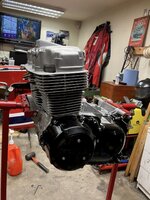
Another update, making steady progress. I've now got the bottom end assembled and buttoned up. Have checked all the ring gaps and ring side clearances on the pistons and all with in spec. All pistons are now on rods and ready for barrel assembly tomorrow. Hope to have basic long block completed by early next week and then back in frame, happy days!
If someone could could correct the wonky picture layout it would be appreciated!
If someone could could correct the wonky picture layout it would be appreciated!
Attachments


Going better than expected, all that's left of the long block is oil pump, sump plate and engine paint. For me its been an interesting project.
Once again if someone can help with photo alignment it would be appreciated
Once again if someone can help with photo alignment it would be appreciated
Attachments


Similar threads