1992 R80GS PD = switched live, without ignition interruption?

sidkn33

Active member
UKGSer Subscriber
Joined
May 18, 2021
Messages
168
Reaction score
53
Location
Surrey England
Hello all,

I have an Acewell speedo on my R80GS PD which needs a switched and a permanent power source - the latter for the onboard clock to keep time.

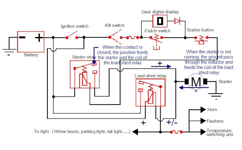
To avoid my speedo "rebooting" between ignition on and firing up the engine (because pressing the starter button interrupts power to every switched live source I have located using my voltmeter and therefore reboots the speedo every time I start the bike) is there a switched live that does not get interrupted by the start button/starter motor?

My amateur attempt to decipher the Haynes wiring diagram has failed.

Any suggestions?
 
The spare terminal on the ign switch should be perm live.if not you can piggyback of the perm feed onto the switch
Ah yes, that's a great suggestion. Thanks.
Is that feed wire anywhere easier to locate than underneath the instrument housing as I don't have everything apart and it's fiddly as frick getting under there.
Maybe at the front of the frame where the loom splits?
 
Ahh ok,,it’s a pd.
The ignition switch on a pd has a loom attached to it .
The red wire is permanent live.
There is also a red/white wire going to the clock/additional instruments connectors ,this is permanent.
The red/ white wire also goes to the turn signal unit ,you could hook into it there as well.👍
Who needs a voltmeter when there's a mikeyboy on hand at UKGSER?!
Seriously. thanks a bunch for the helpful info.
 
Ahh ok,,it’s a pd.
The ignition switch on a pd has a loom attached to it .
The red wire is permanent live.
There is also a red/white wire going to the clock/additional instruments connectors ,this is permanent.
The red/ white wire also goes to the turn signal unit ,you could hook into it there as well.👍
Hi @mikeyboy
Again thanks for the suggestions.
Unfortunately, the red/white wire going to my indicator relay (and presumably therefore the one feeding the clock and additional instruments) is not permanent - it is also disconnected from power by the starter button.
On further examination, it seems the speedo is currently wired into what appears to be the additional instruments + as it is direct from the front of the frame out of the main loom and when I turn the lights off, the speedo loses power as well as its backlight.
I'm not hugely fussed, it was just an annoyance that the speedo rebooted every time, but I'll live with it, in the absence of any discoverable or easy to access permanent, switched live.
You’ve either got a wiring fault or someone’s been messing
 
I can't see any sign of messing, the loom is generally intact and original, all components/relays are in the normal position and functioning - no other faults evident.
It's a weird one.
Any idea what someone could have done to cause the red/white switched live wire to cut when the starter button is pressed, if this wasn't the factory setup?
 
Ok we are into 'what ifs' here as the bike wiring system is not acting as designed. My 'what if' is that the threshold voltage at which the speedo operates is higher than the voltage drop experienced when you hit the start button. So this means there is a weak battery or some high resistance in the starter motor circuit (high power circuit).

You can test this theory, if you want, by putting a voltmeter across the battery when you start the bike.

I've not had time to dig deeper as yet, but not sure I understand "not acting as designed"?-
The headlights on the GSPD are designed to shut off on starter button press and my assumption is that this means zero or close to it, volts for that circuit/feed.
What's happening in my case, is the starter button is affecting other 12v live wires that it apparently shouldn't - I don't think my speedo is rebooting because it's not getting quite enough juice and would otherwise work, the voltage cuts completely for the duration of the starter button press - that's observable on a voltmeter on all the switched live wires I have tested.

I am not an electrician and don't know much about relays etc, other than very basics.

My battery is <6 months old, always cranks healthily and is trickle-charged routinely and it's health doesn't appear to affect the behaviour of the starter button/speedo reboot.
 
I found this K series summary of how a shedding relay works with the starter

"The way that the load shed relay works is confusing but in fact cleaver.
The relay coil is fed with the positive(+) from the ignition switch on one side and from the ground(-) coming from the starter on the other side(the ground is passing through the inductor of the starter motor). when you push on the starter button, this ground will be switched to positive and the load shed relay coil will then be fed by a positive(+) on both sides (This is like not having power). At this point, the load shed relay will be released and the lights and accessories will go off."


Is that about the same as on my GSPD?

There's also a simplified diagram

1748950798052.jpg
 
Can’t help with the above I’m afraid,
I’m only going off the wiring diagram in front of me.
And looking at that,the fused feed to the clock and aux instruments is spurred straight off the main feed so shouldn’t be affected by the load shedding relay,(it’s the permanent feed for the clock so why should it?)
Time to get the test light or multi meter out!

One thing I do know,
I wouldn’t be looking at the wiring diagram for a k bike ,if I wanted to diagnose a fault on a GS
I was Googling how a load shedding relay works and happened upon the k-bike forum - seemed likely that the design would be similar enough - the principle to reduce/cut load on the starter circuit by temporarily removing non-essential supply to high-draw components (e.g. lights).
Of course BMW may have designed something fundamentally different for the K bikes - that's why I shared the info, to ask if it is that different.

Regarding the spurred feed for the clock - yes, that makes sense - you wouldn't want that interrupted every time you started the bike.
 
One thing though, why would there be an auxiliary instruments feed on the later GS/ GSPD bikes when there's no room for the clock/voltmeter to be mounted anywhere.
View attachment 415409Follow the red wire from the battery,
It goes directly to the fuse box via a spur.
Then feeds the clock etc via a fuse.
Is that a Clymer diagram?


Back
Top Bottom