Autocom supply for 2004 1150gsa

Stirfry

Registered user
Joined
Oct 2, 2007
Messages
22
Reaction score
0
Location
Lincoln
Just confirmation really before I hack into my loom.

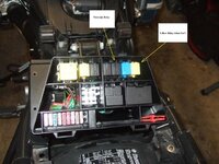
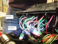
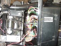
GSrich recommends splicing into an ignition fed wire under the fuse box - a thick green/black wire. I've located two (by thick I assume the 1.5mm2 wires).
One fed out of the Motronic relay, and one from a yellow relay, the function of which is a mystery as it's not shown on the wiring diags I've got.

So, does it matter which green/black? Being the same colour code they're probably joined somewhere anyway, but just want piece of mind

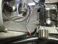
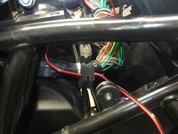
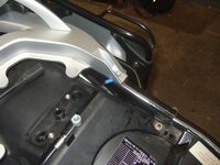
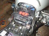
I've attached some pics for clarity
Cheers,
Al
 

Attachments

  • DSCF4061a.JPG
    DSCF4061a.JPG
    48.2 KB · Views: 425
  • DSCF4064a.JPG
    DSCF4064a.JPG
    50.4 KB · Views: 420
Al,

As long as the wire is the thicker version you will be fine, from memory I think there is a slightly thinner one in the loom itself.

Rich :beer:
 
Thanks for that Rich - I've gone with the thick green/black out of the Motronic. I think the extra fuses and relays must be prewired for optional extras (fog lights/ heated clothing? - some one will be along to tell me!)

Couple of pics to show how the fitting went. May be of use to others as a step by step guide.

1.Decided to mount on top of the airbox - diagnostic plug to be moved, and the raised mouldings by the airbox lid screws to be removed to give a flat surface. (wonderful tool a Dremel!). Picture shows autocom powerlead and connector.

2.Routed the Autocom power lead into the fuse box through the existing main loom grommet (there are spare holes in the grommet which can be used)

3.Red Autocom power lead spliced and soldered into the 1.5mm2 green/black ignition switched wire out of the motronic relay. The green/black wire was stripped back with a hot knife attachment on my soldering iron.

4. Earthing point - The fuel tank rubber mounting fixing screws didn't provide an earth as they are mounted in a plastic block. Apart from the battery direct, this was the closest. The battery was discounted as any connecting wire running forward towards the front of the bike would interfere with easy control box removal for access to the air filter.

5.Autocom control box mounted, wired up and working. The unused aux cable and the slack in the riders cable clipped on top using the clip supplied. Passengers cable routed back to underneath the passsenger seat.
The control box can be easily removed from the airbox lid when required, thanks to velcro attachment and all connecting wires running towards the back of the bike.
 

Attachments

  • power connector.JPG
    power connector.JPG
    25.1 KB · Views: 376
  • grommet.JPG
    grommet.JPG
    22.1 KB · Views: 375
  • splice.JPG
    splice.JPG
    58.5 KB · Views: 375
  • earth.JPG
    earth.JPG
    22.3 KB · Views: 374
  • fitted.JPG
    fitted.JPG
    30.9 KB · Views: 376
Or just tap into the fuse for the horn (#4 I think). When the ignition is off the power to the Autocom is cut. Very simple and effective. :thumb2
 
I took the power for mine off fuse 1, which on your 1st photo is the fuse on the left (taken from the top of the fuse looking at the photo, green and black wire i think)
this gives the autocom 4amp protection.. I wish I had taken some piccies when it was in bits, but really dont fancy going in there agin :blast
 
Aidan/Rubberscrubber - you're right more than one way to skin a cat.

Horn fuse method - considered this i.e four male/female crimp connections and short length cable, but decided to have just the one soldered joint.

Fuse one - 0.75 mm2 green/black, this is the supply to the brake light switches and your correct, there is the added bonus of fused protection. I just went for the thickest cable I could find and wasn't too bothered about a protected feed as the control box has built in short circuit and thermal overload protection anyway.

As far as i can see, all methods are fine, the horn fuse method probably being the less intrusive but not the prettiest. (if you're anal enough to be bothered about a connector hidden under a lid which is under the seat!)

Does anyone have a wiring diagram that shows the two extra fuses and the extra relay on my 2004 1150gsa?
 
I just done a few mods to mine, lighting and some power supplies, all run from the fuse box and all relays fuses contained in there, what a pain in the bum, but it does look neat and out of sight,
ref. the wiring diagram I have only ever seen the 2000 GS diagram which seems to fit mine (2001 and my mates 1999 heap)
 
well done - thanks for taking the time :thumb2

I need to get started on mine - just need the courage to start hacking away :blast
 
I'm glad the pics etc are of some use to others - however, just read it again and their is a slight error;

4. Earthing point - The fuel tank rubber mounting fixing screws...
should of course read
4. Earthing point - The seat rubber mounting fixing screws....

I was also wiring in a GPS at the same time and had the tank tilted up and forward for running wires through and access to the battery - must have got all confused when writing the post.:blast

Can a moderator alter the original? (I note that there isn't one for the Bike Comms section otherwise I would have pm'd him)

Cheers,
Al


Back
Top Bottom