Well, I can't post the photos (yet), but here is the text...
You will need…
10mm socket
Selection of Allen socket drivers to fit Torque wrench
Torque Wrench capable of 12-48 NM
Medium file (or coarse sandpaper)
55 Torx key
30 Torx key
You may need…
10mm spanner
Large Rubber Mallet
Block of 2x2 inch wood approx 18inches long.
Trolley jack
RHS = right hand-side of the bike when viewed from the front i.e. the bike’s near-side
LHS = left hand side of the bike when viewed from the front i.e. the bike’s off-side
1. Study the supplied instructions – mine were in German – the important thing is to unpack all the bolts, spacers, washers etc and measure each one (especially the spacers) – find each on the diagram and place ready for use later.
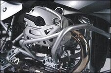
2. Dry fit the bars off the bike first. You will probably need to file/chamfer the ends of the middle section to remove the paint, and use a dab of grease to enable a smooth connection. Once together dry, also insert and screw in half way the bolts that join the middle section with the end sections – this removes the paint from the threads inside the middle section and makes it easier to do up later. NOTE that the middle section has two welded brackets on it – the longer one goes to the RHS.
3. Bike on centrestand with room to work both sides.
4. Just under the RHS of the fuel tank there is a small Torx 30 bolt attaching an oil feed pipe to the engine – remove this bolt.
5. Loose fit middle section – the LHS is bolted to a captive nut that is part of a (black) bracket already on the bike just under the LHS fuel tank using the shorter M6 allen bolt. The RHS is bolted where the Torx 30 bolt was removed from above with the longer M6 allen bolt together with smallest spacer. Do the allen bolts up finger tight.
6. NOTE – do not remove both Torx 55 frame/engine mounting bolts at the same time – not sure what would happen but I suspect it would not be good.
7. Remove RHS Torx 55 engine mounting bolt. Insert appropriate spacer (just stands approx 1-2 mm proud) – offer up RHS section of bars – with a (limited amount) of twisting, use of rubber mallet, force the RHS section of bars onto the middle section – may need more grease – ensure the holes of the RHS bars are near where they will be bolted i.e. you don’t want to damage anything while concentrating on the mallet action.
8. Loose fit (finger tight) the connecting 10mm bolt (NOTE that I didn’t do this until last and had to mess about with a trolley jack, block of wood and a larger rubber mallet to get the holes to line up).
9. Loose fit (finger tight) the large replacement M12 allen bolt.
10. Fit the other spacer and M10 allen bolt to the RHS in the (empty) threaded hole. Finding the correct angle of attack for sliding the spacer between the bars and engine can be tricky, still, the sump bash plate usually catches it and provides a small entertainment poking it out with a stick.
11. Eat bacon sandwich provided by your wife.
12. Repeat the procedure for the LHS section of bar – where this joins to the middle section there is a slotted hole. Again, may need trolley jack etc to line up holes for the 10mm connecting bolt.
13. Tighten to torque the 10mm connecting bolts.
14. Tighten to torque(s) the lower M12 and M10 allen bolts both sides.
15. Tighten to torque the upper M6 allen bolts both sides.
16. Admire handiwork, realise that coffee provided by wife along with bacon sandwich has gone cold. Drink it anyway.
17. Re-check torques after a bit of mileage.


 Fitted H&B bars this afternoon, your excellent writeup saved a lot of necessary swearing
