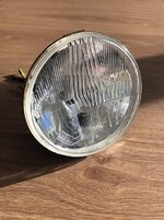
For future reference, the sealed beam headlight for a Lotus Elise is 150mm. It's a concave Cibie and fits in the original shell. Takes an H4 bulb.
Sent from my SM-G925F using Tapatalk
Sent from my SM-G925F using Tapatalk


")

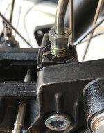
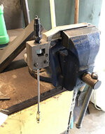
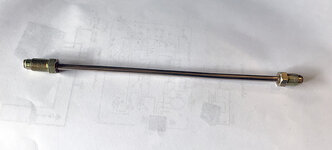
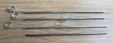
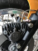
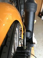
 System bleed and no leaks, not one. I have to say I was well chuffed