- Joined
- Jul 23, 2004
- Messages
- 2,373
- Reaction score
- 124
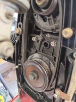
Made one these these up to check position of my new sensor plate even though marked off the old one before removing. Lights come on when turning pulley wheel bolt at 180° to each sensor.
If anybody wants to use it, let me know and I can post off.
Based near Nantwich.
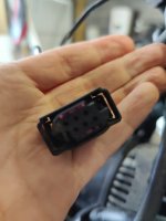
Fits onto both flat and rectangle plug.

Sent from my MI 9 using Tapatalk
If anybody wants to use it, let me know and I can post off.
Based near Nantwich.
Fits onto both flat and rectangle plug.

Sent from my MI 9 using Tapatalk
")