Micro DE to HiD Convertion Kit

As above. I did ask last time I was in and got the response above.

I think the DE spots have too small a reflector to give a really good light spread.

Other option would be some 6" or 8" cibies, now they would be mental mental chicken oriental in terms of light spread, knock a good 10 mph off ya top speed though :D:D:D
 
Only done the fog's at the moment, would have to find out if the supplier does the spot ones.

And have now done the FF50 HiD :cool:

I would sure love to have my FF50's also converted to HiD:bow:. But i'm running out of places to stash the Ballasts:confused:. And any more weight over my front wheel will make my wheelieing antics harder to perform ;)

:D:D:D:D
 
Four ballast bracket and then one each side of the tank panels :D
 

Attachments

  • ff502.JPG
    ff502.JPG
    41.9 KB · Views: 818
Update: I got a set of the conversion discs from Les a while back but with hols'n'stuff didn't get round to fitting them until last weekend.

The end result is bl**dy excellent.

The job is easy enough to do, the only tools you need are a Torx T10 screwdiver bit and a Stanley knife. Depending on the make of your HID burners you may need to file the centre disc a tad.

If I hadn't already acquired an H3 HID kit I'd have sent the Micro DE's to Les for conversion, but DIY with the discs worked out fine.

Top stuff - thanks Les. :thumb
 
I've finally made a start on the conversion.
I've done one unit and just chucked it on to do a comparison.
IMG_3266.jpg


The one on the left (i.e. the offside of the bike) Is a converted HID Hella Micro DE and the one on the right (nearside) is the standard 55W Hella Micro DE.
Headlamp has already been converted to HID some time ago.
Standard lamp looks rather weedy in comparison.
 
HID micro DE's

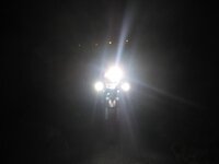
Just finished fitting my "Wassellised" HID micro DE's. In all honesty not a job I've greatly enjoyed, but after a brief stationary ceremonial switching on I think the results will be worth the effort. The job probably took me the best part of 8 hours, a significant proportion of which was devoted to cursing the guy who designed those bloody side panel fixings (specifically the internal bottom front ones) and weighing up where to stuff the large 2300 V black boxes that I wasn't expecting to find in the cable from the ballasts to the lights.
My thanks to messrs Wassell (for the lights & advice), Yonkyo (for more advice on black box location), Rolf for the idea of where to mount the switch and the author of the website: http://www.bmwman.biz/ for a guide to fitting aux lights and providing the link to http://www.vehiclewiringproducts.co.uk.

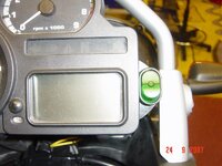
FWIW here's my set up. I made up an alloy bracket to mount the standard Hella switch (same as the one Wunderbra supply with their spotlight kit apparently) alongside the instrument cluster. The bracket is attached with double sided tape (Duck brand with a cloth weave in it) to the underside of the instrument panel.

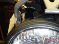
I picked up the supply from the dip beam to the switch by scotchlocking inside the headlamp unit and leading the cable out through a hole drilled in the bottom of the bulb cap. Like the website author, I used yellow wire for the dip beam feed and red from the battery via a 10A waterproof fuseholder to the relay. All bits sourced from vehicle wiring products including somw rather smart cable sheathing. They sell sheathing & wire by the metre which is handy.

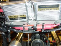
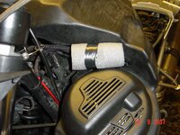
The ballasts are mounted on an aluminium plate I made up to bolt to the MiGSel bar (top quality piece of kit).

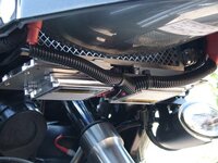
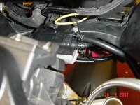
I tried to follow Yonkyo's advice on black box location, mounted axially on the front fairing support Y bracket, but couldn't find a wiring configuration that worked. In the end I settled for taping them together back to back and mounting on a pipe lagging sandwich transversely just behind the light unit. Means I can't use the beam adjustment lever but I've never needed to.

The rest of the HID wiring, plugs etc is cable tied to the back of the MiGSel.

Main cock up was the relay location. I had decided on a location out of the way to the front left of the fuel pump, but after cutting all my cables to length and fixing the relay I discovered the forks rubbed against the wiring on full lock! Cables not long enough to change the route so ended up with the relay well taped up & cushioned with pipe lagging wedged in the gap between the fuel pump cover and the tank. Pretty it isn't - I hope it works!

You need patience to do this kind of installation; re-reading Zen & the Art might have been a good idea before I started.

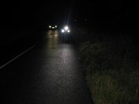
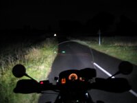
Anyway. they're on now and they work. All that's left to do is sort out an adjustment that doesn't blind oncoming traffic but ensures I get seen.
 
The missing photos ....

Don't know what went wrong - I uploaded 5 photos to go with the above message but they have not materialised. 2nd service ...
 

Attachments

  • DSC02947.jpg
    DSC02947.jpg
    66.6 KB · Views: 633
  • DSC02949.jpg
    DSC02949.jpg
    47.7 KB · Views: 632
  • DSC02944.jpg
    DSC02944.jpg
    87.4 KB · Views: 629
  • DSC02946.jpg
    DSC02946.jpg
    64.4 KB · Views: 628
  • DSC02950.jpg
    DSC02950.jpg
    82.2 KB · Views: 629
Glad you got it sorted Paul, it's a shame you did'nt take advantage of my fitting service and pop over, we could have nocked it all up in a couple of hours :augie

:D
 
Fitting service

With the benefit of hindsight, perhaps a trip to sample the delights of Congleton might not have been a bad idea. It's not that it's difficult or complex work, but there must be a significant benefit in having the experience of knowing in advance where best to put things. For example I agonised for ages over the switch location and then over the method of fixing - I tried velcro first but that was a disaster.
Also, it was the first time I had stripped all the panels, beak & screen off the bike. That in itself took me far longer than it will next time. I also removed the tank which I suspect I could have managed without. Silly things like deciding on fuseholder & relay location all take time and as for those bl**dy black boxes .....

Any way, thanks again for the conversion job and to anyone thinking of a DIY installation, give the LW fitting service some serious thought!
 
With the benefit of hindsight, perhaps a trip to sample the delights of Congleton might not have been a bad idea. It's not that it's difficult or complex work, but there must be a significant benefit in having the experience of knowing in advance where best to put things.

Nice one for having a go :thumb2

Les really has got it sorted, the solution as a complete package is superb. When I was over there with my bike it was a quicker job than having tyres fitted! Ride in, ride out :bounce1
 
Wassalised 1150

Been over to see the HiD Mistro today and had my bike Wassalised.

Having struggled back to a campsite over the Yorkshire Moors at night and in the rain with the Pi** poor standard lights I can confirm that this is the best mod you could possibly consider.

Les converted my Micro DE`s to HiD and did the same trick to my dip beam light. This lad knows his stuff with these units and does a neat job at a ridiculously low price!

To top it all off I was made to feel welcome with supplies of tea and a new culinary experience for me .. "Hot Staffordshire Oatcakes filled with cheese!"

Been out playing in the dark for the last few hours with my new lights....
 
Wassalised ...

Took this picture on a country lane just as a car passed my bike ...... look how much brighter my lights are to his..!
 

Attachments

  • IMG_0492.jpg
    IMG_0492.jpg
    35 KB · Views: 591
Wassalised ...

Another picture showing the intensity of the new HiD modded lights ....
 

Attachments

  • IMG_0496.jpg
    IMG_0496.jpg
    29.7 KB · Views: 590
Wassalised ...

One more ......
 

Attachments

  • IMG_0497.jpg
    IMG_0497.jpg
    16 KB · Views: 592
Does the HID DE upgrade require an uprated fuse?
I've fitted mine and left the original fuse in place (can't remember the rating offhand) but after a couple of uses it seems to have blown.
 
Does the HID DE upgrade require an uprated fuse?
I would have thought a fuse that worked for 2x55W filament bulbs would be OK to power 2 x nominal 35 W HID's.
If the 35 W nominal rating per lamp is a correct appraisal of the total power consumption characteristic of each HID at a nominal 12V, then the system should draw 5.8 amps max. Given that the actual system voltage is likely to be greater than 12 V then I guess the actual current & power could be ~10% higher than that. However being unsure of the exact circuit parameters of the HID system compared with normal filaments, to give some headroom I fitted a 10 amp fuse I had spare in my car. So far no problems.

Cheers
Paul

Makes sense. I'll have a proper look at the weekend.
I just windered if the initial start-up might require a higher rating? :nenau
 
Makes sense. I'll have a proper look at the weekend.
I just windered if the initial start-up might require a higher rating? :nenau

If the fuse goes it seems to be the initial start up, I increase the 7.5 in the ADV to 10 amp and it seems good then.
The AUX fitted DE's onto a custom loom which usually goes to the battery via relay, I would still go 10amp.


Back
Top Bottom