I read somewhere that the user of the handheld radio is the groundplane.I do believe that the rubber antennas that come with the radios are GPI, can't see it any other way, even with the alloy chassis.
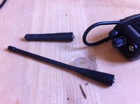
Correct, it is the contruction regs that don't allow the manufacturers to produce them with removable antennas. In the early days of the radios I believe the regs also didn't allow modification after construction but this was changed a few years ago.When people say that it's illegal (i.e. against OFCOM regs to use an external antenna) they aren't correct.
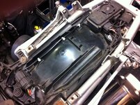
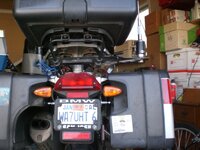
+1Regrettably this is incorrect. Whip antennas radiate their power in an approximate doughnut shape. Not with a hole in the middle but certainly dimples... So with a radio on it's side under the seat and inline with the axis of the bike, you might get reasonable Tx to each side, fore and aft it would be poor. Similarly, across the axis fore and aft would be reasonable, side to side poor. Added to which you have lots of gubbins in the way and are iradiating you testies, prostate etc...
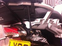
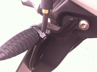
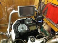
Though increasing the power will increase the range in all directions, especially due to the signal being reflected, but the best solution is to get the antenna mounted vertically.
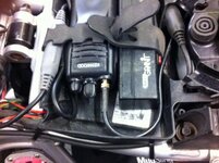
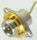
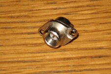
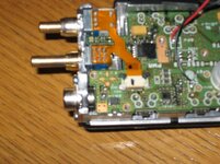
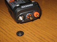
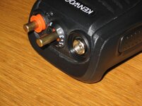
Regarding the parts you need to modify the radio, I think Bumpkin's link in an earlier message leads you to the parts, but just in case it doesn't look at this post.
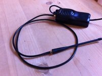
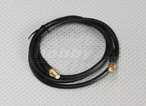
What is important is to use as few connectors in the antenna set up as you can. Each connector has the potential to lose approx 0.5 dB of power. In your post above (post #18) you have 4 connections and, therefore, the potential to lose up to 2 dB in power (a 3dB power loss represents half the power). You will get more radiated power, and therefore more range if you can reduce the connectors, and this can mean a lot with the low power of PMR radios. On my set-up I have just one connector, at the radio, the coax is connected direct to the antenna.
The antenna I used is the 0058 on this page (or click here for full details). Renair will cut the antenna to the correct length to optimise it for the PMR band, they will fit the required length of coax you need, and whatever connector you need for the radio (SMA if you use the connections mentioned in the link above).
This arrangement increased the range of my radio broadcasts by more than a factor of 4.
Bob

")