12GS Fender Mods - Revisited
Sorry for taking so long to get back to this. My only excuse was that the bike was being ridden and not available for the disassembly required to make the more detailed instructions. I now have over 25000 kilometers using this set-up, and can attest to its effectiveness.
At the same time, I replaced the old forward rear fender, with one fabricated from a new UFO Universal Front Fender #PA01013, in black plastic (I had to paint the original one). UFO Plast (
www.ufoplast.com) is an Italian firm, so they should be available in Europe.
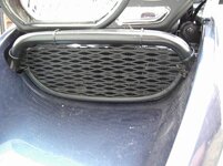
This opportunity also allows me to clear up a possible misconception from the original photographs. In the shot showing the tyre to fender clearance, the rough inside surface of the fender possibly appears to have been contacted by the tyre. (This roughness was from a previous repair to the fender that caused it to be scrap in the first place.) For over 25 thou km, I haven’t had any contact between the tyre and the fender. There is some chafing evident between the fender and the shock shroud, which has now been mitigated with the use of an anti-chafe pad or tape affixed to the shroud.
Otherwise, these rear fender modifications have been proven to be extremely effective at keeping spray and crap from the rear wheel off of the exhaust pipe, swingarm, shock & shock pivot, transmission & battery, not to mention the back of the rider’s legs. Additionally, there has been no damage to the bike (apart from the shock shroud abrasion and the holes for mounting the forward fender) so that all modifications can be painlessly reversed if desired.
Forward Rear Fender Instructions
The fender I used for this modification is a UFO Universal Front Fender in black, UFO# PA01013, although other 21” fenders may fit.
1. Cut the front of the fender immediately forward of the notch for the fork legs.
2. Make a “U” shaped cut to eliminate the remainder of the wiring tunnel in the top of the fender. Make the cut wide enough to allow the GS toolkit strap to fit in. File and smooth cut edges.
3. Position the fender on the curve of the toolbox underside, immediately below the raised rib on the toolbox, so that the fender extends between the tyre and the swingarm pivot. The fender may be shortened slightly to give more tyre clearance if required.
4. Mark where you wish the mounting holes to be, making sure you do not compromise any components on the inside of the toolbox. Drill holes to size of bolts that will be used.
5. Place some tape or glue some sheet rubber on the shock shroud where the fender touches it, and mount the fender.
6. Some adjustment of the fender can be achieved by placing washers on the mounting bolts between the fender and the toolbox. Place the washers under the top mounts to move the bottom lip of the fender forward (against the shock shroud), and under the bottom holes to move it closer to the wheel.
RS Fender Instructions:
1. Resizing of the image in your word processing or photo software may be necessary to get the printed template dimensions of 7 5/8” long, and 2 ¼” wide (dimensions are point-to-point). Ensure you maintain the proper aspect ratio when resizing.
2. Cut out the template using the outer lines. The template is for the left side of the RS fender, simply reverse it to mark the right side. Use tape or temporary sticky putty to hold it in place on the fender.
3. The edge “B” is placed along the top edge of the contour that divides the fender in half, wrapping it around the corner from the side to the rear. Edge “A” is placed flush with the side forward edge of the fender. Transfer edge “C” to the fender as the line to cut the top part of the RS fender away.
4. Repeat step 3 for the left side of the fender.
5. Draw a line on the fender along the top of the contour, between the inner points of the template markings. This contour will fit over the top edge of the GS bracket for proper positioning. See photo for explanation.
6. Ensure the cutlines etched onto the fender are accurate and symmetrical. Remove the material above the lines you have scribed. Cut outside the lines (allowing extra material for exact trimming) with a jigsaw or scroll saw.
7. Fit in place and trim for best fit, smoothing all cut edges with a file or sandpaper. The forward ‘wings’ of the modified fender fit between the inner fender and the tail section bodywork.
8. Place two ¼” thick spacers between the modified fender and the LP bracket to allow for the thickness of the mounting contour of the fender.
9. Attach the modified fender using your existing LP carrier, however, longer screws may be required. I used M5 x 23mm screws and self locking nuts. For the smaller North American LP carriers, only two bolts are required.
10. Fill in extra holes in RS fender with reflectors, decals, etc. as you see fit.
Here is the template for cutting the RS fender:
I hope this helps.
Cheers


")


 In sticky mud though, this does the business.
 I haven't got the wherewithal to post pictures of the reults, but I can assure you that it has made a significant difference. Before the front of the swing arm and the shock cover would be liberally covered in mud, and this would be further displaced by any water to end up all over the back of the bike. Now it is only caked on the underside of the additional guard and the top of the centre stand.