Ta for that. Just heading for Specsavers ...
Ha ha.
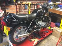
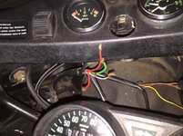
Anyway, nearly there I think. Just need to sort the cable runs and finish the fuel connections and tomorrow I could be ready to try running it!


Ta for that. Just heading for Specsavers ...
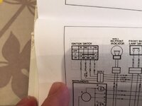
else I would have had to engage the services of an auto electrician; I don't have the skills for tracing.

Hey, Well done.
I'm impressed that you kept on and that you were able to finish this in what has obviously been difficult circumstances.
The bike is a credit to you....plain, simple and understated.
One question though, and please correct me if I am wrong, no offence will be taken.
Front forks.
Have you reassembled these back to front?
I always thought that the wheel spindle head was on the offside with the locking nut on the nearside. Also, the calipers were always behind the fork leg, or have you done a larger disc conversion?

Hi Dr Nosh, thanks for the comments. I can see why you think that about the forks but the calipers are correct for the monoshock. Also, the wheel spindle head is on the offside.

Hi Folks
I've had a problem with a leaky rear main seal since putting the bike on the road and it was bad enough that I had to fix it.
I've got a few questions if anybody can help:
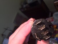
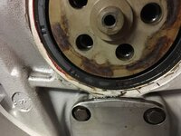
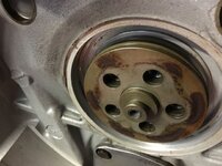
There should be an O ring somewhere between the flywheel and the crankshaft. I've taken the seal out as shown but is there a removable plate with an O ring underneath it?
I don't want to force it to try and separate it and that brings me to my next question, do I need to replace the O ring if it's there? Could this be a source of the leak?
Would I need to remove this plate to get the seal to mate properly i.e. put the seal in and then the plate afterwards.
I've ordered the "later" lipped seal from Motorworks. Should I soak this in oil for a few hours before installing and if so should I then fit it 'dry' ish?
I really want to get this right as I don't want the hassle of taking it apart again so any tips much appreciated
Cheers
David
What he saidThat "boss" your looking at in the picture, the goldy looking one with the 5 holes and protruding centre piece...... that pulls off the end of the crank. Inside is the "O" ring you're looking for (usually red in colour).
Replace it, even if it looks ok.
Let the new rear crank seal soak in oil for a while before fitting it. Then push the "boss" back in place which bends the the ribbed part of the seal to fold backwards and to seal against the boss .
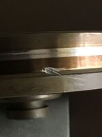
One thing to beware of when doing all this, in fact you should have been aware of before you've got this far... The crank thrust washer can drop off it's locating dowel very easily... You don't want this happening as it's not good, and you'll be cursing yourself for weeks, nay months..
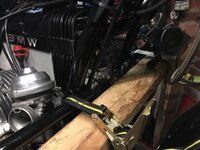
What you got to do is be very careful pulling that boss off, you don't want the crank moving, at all.
So remove the front engine cover, and using a piece of wood/plastic of the appropriate thickness 10mm or so , place it onto the front of the alternator stator and refit the front cover on top of it, so the crank is held pushed back in the case leaving you to get on with removing the "boss" without a care in the world.

That "boss" your looking at in the picture, the goldy looking one with the 5 holes and protruding centre piece...... that pulls off the end of the crank. Inside is the "O" ring you're looking for (usually red in colour).
Replace it, even if it looks ok.
Let the new rear crank seal soak in oil for a while before fitting it. Then push the "boss" back in place which bends the the ribbed part of the seal to fold backwards and to seal against the boss .
One thing to beware of when doing all this, in fact you should have been aware of before you've got this far... The crank thrust washer can drop off it's locating dowel very easily... You don't want this happening as it's not good, and you'll be cursing yourself for weeks, nay months..
What you got to do is be very careful pulling that boss off, you don't want the crank moving, at all.
So remove the front engine cover, and using a piece of wood/plastic of the appropriate thickness 10mm or so , place it onto the front of the alternator stator and refit the front cover on top of it, so the crank is held pushed back in the case leaving you to get on with removing the "boss" without a care in the world.
 Terrific advice from Steptoe and Mikeyboy. To think that some folk begrudge paying their sub to this forum!