Bleeding rear brakes

Still it goes on...

At last I've got the missing bits for the caliper, bleeding them should have been a doddle with the help I've had from here.

Well, I'm still having problems.

The root cause seems to be that when I release the pedal the air is still sucked in

John, It sounds very much like you're not fully closing the bleed nipple arfter each press of the peddle prior to relasing it (ie before letting it spring back up). Hence air being sucked back in :nenau

Failing that your thoughts on replacing the seals in the master cilinder would be a good idea.


Val.
 
John, It sounds very much like you're not fully closing the bleed nipple arfter each press of the peddle prior to relasing it (ie before letting it spring back up). Hence air being sucked back in :nenau
Val.
No, it doesn't matter how long I keep pumping the pedal for, as soon as I open the nipple it will suck air (or fluid) back in. As far as I can work it out this is wrong as all that is happening is that it's just pushing fluid in and out rather than pumping it through.

When the pedal is released the piston in the master cylinder should uncover the port from the reservoir and draw a fresh charge of fluid into the cylinder. When I stripped the master cylinder I found some gunge in it and I'm wondering if this gunge was stopping the piston from reaching the end of its travel so that the port to the reservoir was not being opened. Just before stripping it I measured the distance of the piston rod from the end of the master cylinder casing so that I can compare it with its position after overhaul.

One important point is that there should be a clearance of between 1.4 and 1.5mm between the operating lever and the end of the piston rod. Whether this is crucial to within 0.1mm I don't know, but there ought to be some slop there to ensure that the port from the reservoir is uncovered. As to how on earth we are supposed to measure this gap I have no idea- FFS this clearance is in a recess in the end of the master cylinder, it's covered by a rubber cap and it's a hell of a job to get at the thing when in its position next to the swing arm. So I've nipped a bit of welding rod (OK, it's 1.6mm, but what the hell...) as a gauge in the gap, and measured the more accessible gap between the operating lever and the the master cylinder casing, see diag. As I haven't assembled it finally yet I won't give you the measurement and the chances are that it would be different on yours anyway.

So, once I've put everything back and reconnected the link and brake lever I can adjust the gap and check the clearance by making sure that this other gap is what I originally measured it as: i.e. if this "tell-tale" gap is correct then the lever-to-piston rod gap (the 1.4-1.5mm one) will be correct. Anyway, I promised myself I wouldn't draw another diagram. Here it is. :blast

The overhaul kit should be here tomorrow, I'll keep you posted
 

Attachments

  • Tell-tale 4 cutaway.jpg
    Tell-tale 4 cutaway.jpg
    41.1 KB · Views: 99
  • Tell-tale cutaway flattened copy.jpg
    Tell-tale cutaway flattened copy.jpg
    45.5 KB · Views: 100
Last edited:
The overhaul kit should be here tomorrow, I'll keep you posted
We-heey, job done. Took it for a blast just now, the brakes brake, the gears change, everything works. First ride since November, happy as a pig in shit, teeth full of bugs.

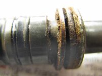
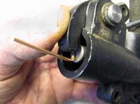
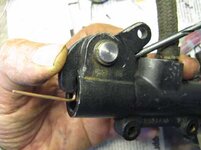
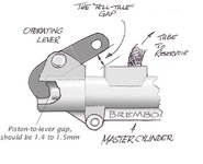
So it was the master cylinder then, gunge was preventing the piston from coming all the way back. There was some in the calipers too, but nothing like in the master cylinder. Oh, I checked the Tell-tale clearance, it was 4.2mm in mine, I checked it with a drill from the set I have sized at 0.1mm intervals (that's four thous in old money), apart from drilling holes they are often handy for measuring gaps. Happily this gap can be easily measured when the master cylinder is in position on the bike, just you try measuring the actual gap between the piston rod and the operating lever. I couldn't anyway.

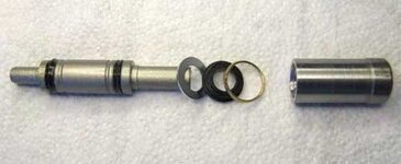
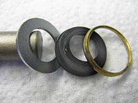
Naturally more grief was to come finding the order in which the seals and washers went on the piston rod, and how they were fitted in position, there were no instructions included in the kit. Darren from Motor Works spent about half an hour with me on the phone, bless him, trying to sort it out, asking other people and he eventually found a drawing from Real OEM.com which he emailed me. The correct order is: Spring, Piston (with the two rings/seals) the plain washer, the black neoprene(?) seal with the writing facing the plain washer, and then the ring that looks like the crush ring that goes under oil filler and drain plugs on the bike. This last ring fits neatly into the recess around the edge of the black neoprene seal. The whole lot is then inserted into the master cylinder, the spring is compressed and the washers are pushed back up to the shoulder that is about a couple of centimetres inside the master cylinder.

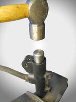
According to Darren people then use a suitable socket in the recess and tap it with a hammer to expand the ring that looks like the crush washer, in expanding it retains the spring and piston in the cylinder. It does the same job as a circlip but without needing a groove. I couldn't find a socket that fitted so I made one in the lathe, ten minute job, if anyone wants to borrow it then it's here for you if you want it.

One rather worrying thing was that the seal was very slack on the rod, it didn't actually grip the rod at all: put it on the rod and fell it off immediately when held upside down. I can only hope that when the crush washer is nipped up and flattened then it has the effect of reducing the hole so that the shaft is gripped, but I really doubt it. It might explain the gunge I had found in my master cylinder.

Bleeding was done with little bother with the vacuum bleeding system loaned by the BMW Club, they have all the special tools needed for working on Airheads (and for all I know, perhaps for all other bikes in the range as well) whether it really needed the vacuum bleeder or not I neither knew or cared, such was my desperation to finish the job. The Tool Hire service was the reason I joined the Club, and it really is good to have the proper tools for the job.

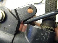
One of the last awkward jobs was getting the ruber boot/gaiter/bellows over the output flange between the gearbox & swing arm, that was done using a tip I got here in the Airheads Section of bending bits of welding rods into hooks, thanks for that whoever it was.

One snag I found on firing up was that there was an oil-leak from one of the rocker covers, I'd stripped the thread on the central stud. I've done search, but no luck, from what I've heard it shouldn't be too difficult to do repair in-situ. How is it done, Helicoil or drill & tap oversize? I may post another thread in the hope that more people will see it. A cut-and-paste, perhaps.

Feck, that first ride was good.
 
One of the morals of this story is change your brake fluid regularly to keep everything nice and clean. I've pulled apart quite a few calipers that appear to have the contents of someone's hankerchief inside :eek:
It's a bit like clean engine oil -cheap preventatve maintenance :thumb
When I get a 'new to me' bike I change all fluids and filters first up regardless of the service history, then I know for sure what has been done :thumb2

Glad you eventually got it sorted -lots of good tips for everyone in this thread.
 
Well done John, glad your sorted :thumb2

I've only had the rocker covers off jill's 100 once, but IIRC a helicoil should see you allright.


Val.
 
Weldone that man:beerjug:
See yer in a couple O weeks for the Wee-Kend.
See my PM earlier today..
:rob

Hi Lyn,

Yes thank you, that was amost generous offer of yours but the brakes are finally sorted. As my PM box is full and I hate deciding which messages to delete then I might as well reply here.

The latest wee problem is the centre stud holding the rocker cover in place- you've probably seen my moan elswhere on the Airheads Forum. A mate just down the road has some and he will let me know when he gets home this evening if he has something suitable. TBH it doesn't have to be a metric thread where it goes into the head, it should never come out once it's in anyway. It's a practical approach even though not a purist's approach...

Actually, there is a possible problem with riding that distance to the Wee-Kend: the operation on my hand I had in January, my grip is still weak in my clutch hand, long distance might well be a pain (literally) I'll see how things go in the meantime, leaving the final decision until nearer the time. One possible way forward is to use the BMW Club's vacuum bleeder I borrowed for the brakes and keep squeezing the handle on that as an excersise. As you can see it's a particularly versatile piece of kit. :thumb

In fact, there are two other issues next week, we are having the whole house rewired (sparkies call that house-busting in the trade and I must admit that I'm sorry to have told my wife that by now :eek:) Then there's the small matter of doing my mum's house up in between two tenants, mum herself is in a home by now and quite happily ga-ga, bless her. My turn next, perhaps.

Thank you again, I'll be in touch soon.
 
Maybe worth a try - it worked for me.

Whilst performing my own servo/ABS removal over the last few days, I too had problems bleeding my back brake. Reasoning that the advice here and elsewhere was well worth following (largely it has been very useful I have to say), I removed the rear brake caliper to 'elevate' it above the master cylinder - supposedly to remove possible air locks - the obvious one (to me at least) being the new 'highspot' created when fitting the cranked banjo bolt directly onto the top of the master cylinder (yes it reaches, but like others here, I think I'll eventually get around to replacing it with something slightly longer and with a straight banjo connection). Anyway, caliper off and raised, pump, nipple, pump, nipple, pump.....etc etc ...got me nowhere. Did the usual check for tightness on all joints then did something I didn't think I had to do when bleeding brakes (yes alright everyone, if this is what you're supposed to do in the first place, I'm sorry, but I just didn't know).....I took out the black rubberized cup from the master reservoir and along with it all of the fluid..filled the reservoir again and three pumping/nipple cycles later and the pressure was back in the system. I like to rule things out so having refitted everything, I removed the cranked banjo, let a load more air into the system and with the offending black cap back in the reservoir was unable to bleed the system once again. Cup out again and maybe 10 pumping/nipple twiddling cycles later and bingo - pressure and with the caliper refitted! My rubberized cup now has a nice new hole in it to stop it from creating the artificial reservoir that was so obviously causing my problems. Now before you all start screaming at me, I'm reasonably intelligent but I still don't know whether the cup was supposed to be in or out when bleeding the brakes...maybe others didn't know either...and that's my reason for posting. Good luck.
 
A bit more about overhauling the Master Cylinder.

As suggested by Steptoe and VAL H the pedal was not returning fully, and the reason was that the gunge in the Master Cylinder was retricting its travel. See photo 1. As a result the hole (port) in the side of the cylinder was not being uncovered so no more brake fluid was being drawn into the cylinder from the reservoir.

So I got a repair kit, see photo 2, comprising of a return spring, (not shown in the pic, I forgot,) a new piston with the two new seals already on, and three washers and seals. The shiny bit at the right of the picture is the inserter tool I made, more of that later.

There were no instructions provided with the kit and although I could make a reasonable guess at how to go about it I wasn't happy to go ahead. It's my brakes, my bike, my NECK. So after finding out I thought it would be useful to post how I eventually did the job.

Photo 3 is a close-up of the bits showing the order in which they should be assembled on the piston rod. The order being: piston rod - plain washer - black neoprene washer with the writing ('Brembo') facing the plain washer - and then the gold-coloured thin washer.

The bits were lubricated with the grease supplied in the kit (brake fluid would do just fine) and inserted in their correct order into the Master Cylinder. The washers & seal were pushed as far as the step in the cylinder bore while compressing the spring in the cylinder. At this point most people use a suitable socket (socket as in 'Socket Set') to tap the thin gold-coloured washer and expand it in position in the bore of the cylinder, that should retain all the bits in position inside the cylinder. As I couldn't find a suitable socket I made a tool (the one shown in photo 2,) a simple thing, but foolproof, :mmmm 
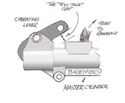
it was just a short length of steel bored out to clear the piston but reaching down as far as the thin gold-coloured washer. The stack of washers were pressed down and held in position and then tapped with the hammer as in photo 4 to expand the washer. As I said elsewhere, if anybody wants to borrow it, let me know.
 

Attachments

  • 1 Gunge.jpg
    1 Gunge.jpg
    22.2 KB · Views: 70
  • 2 Piston assembly, special tool.jpg
    2 Piston assembly, special tool.jpg
    21.9 KB · Views: 69
  • 3 Order of washers and seals.jpg
    3 Order of washers and seals.jpg
    23.6 KB · Views: 74
  • 4 Seating the washer copy.jpg
    4 Seating the washer copy.jpg
    28.3 KB · Views: 70
More about the Tell-tale gap

As I said before in an earlier post, the manual says there should be a gap of between 1.4 and 1.5mm between the lever that bears on the piston rod in the master cylinder.

Whether this has to be rigidly adhered to I doubt but if that is what the good book says then... Of course, it may be that all that is required is a definite clearance without being excessive. But that's just my own idea, make of it what you will. Feedback on this point would be welcome.

Anyway, gaining access to this gap to measure it seems extremely difficult when the master cylinder is in its correct position on the bike. Firstly, the gap is recessed in the end of the Master Cylinder. It is enclosed by a rubber boot. And finally the wretched thing is tucked away between the silencer bracket and the swing arm.

So I made a gauge from a piece of welding rod which was 1.6mm diam, (actually I flattened it a tiny bit with a hammer to reduce it to something between 1.4 and 1.5mm thickness) and inserted this into the piston-to-lever gap, and then nipping it in place with my finger on the lever- photos 5 and 6- I then measured what I call (not unreasonably, I think) the Tell-tale gap. As I said earlier checking this gap is a LOT easier than measuring the actual piston-to-lever gap. The thing is, you don't have to actually measure it, just file a bit of metal to make a gauge that fits into this gap. When you fit the master cylinder back into the frame you can then adjust the gap with the adjustment in the pedal linkage as normal and check it easily with your new gauge. As in photo 7 I used one of my set of drills which are in 0.1mm steps, but as I said the actual measurement isn't that important just as long as it's what gives the correct clearance lever-to-piston. On mine it happened to be 4.2mm, but it could well be very different on yours.
 

Attachments

  • 5 Gauge 1.jpg
    5 Gauge 1.jpg
    24.6 KB · Views: 70
  • 6 Measurement of Tell-tale gap.jpg
    6 Measurement of Tell-tale gap.jpg
    26.8 KB · Views: 70
  • 7 Tell-tale gap close-up.jpg
    7 Tell-tale gap close-up.jpg
    28.3 KB · Views: 66


Back
Top Bottom