Dogbytes' R80 ST project

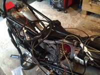
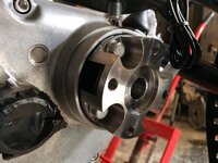
It makes perfect sense to mount the electrics under that huge void you have there, the weight is negligible, the access is almost instant and there's plenty of space to do a really nice job of laying it all out.

Also, never underestimate the convenience of being able to test / fault find the electrics while being able to fire up the motor without removing the tank ;)

I'm genuinely gutted that I'm not doing it for you :tears

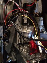
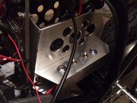
I took those things into account, Chris, when I decided to put it all in the seat hump. It always made sense to put it there from an access point of view but I needed somewhere for the oil catch rank/breather bottle. As it happens, I think by putting the starter relay and the MSD tach converter (neither of which need to be got at readily) under the fuel tank, I can then fit the ignition control box, the fuse box and make a catch tank that'll fit in the remaining space under the seat hump.

I'm gutted you're not doing it too (see pic)!

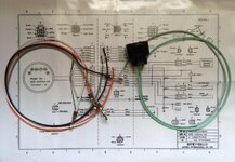
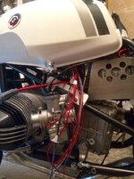
In all seriousness, I cannot imagine what all this stuff is for! I'm from a world of points and condensers. There's what appears to be a Hall Effect ignition trigger and a double-ended coil (presumably wasted spark, so from the ignition system's point of view it's a single cylinder motor) and a black box (okay it's red, but you get my drift) which, I guess just controls it's advance,etc. So why the bird's nest? I imagine all will become clear as I go through it wire by wire.

I'm in your neck of the woods on Monday - to do some work on an anti-aircraft gun. Those I understand. :)
 

Attachments

  • image.jpg
    image.jpg
    76.5 KB · Views: 900
  • image.jpg
    image.jpg
    115.1 KB · Views: 904
I think I've got all the bits in place and have started connecting it all with the electric string provided. I've managed to prune some of the extraneous bits from the Acewell instrument loom and I think I've got my head around how it's wired in. Just have to get a grip of the MSD ignition system now - but I think that'll be simpler.

I've got a couple of the short inlet trumpets from Richie. Not ideal but they fit. It turns out I could probably get the middle-sized ones on it so I think I'll try those, when it comes to dyno time, before doing anything more radical.

HT leads arrived today too!
 

Attachments

  • image.jpg
    image.jpg
    65.6 KB · Views: 855
  • image.jpg
    image.jpg
    76.9 KB · Views: 852
Meanwhile, in another part of the forest...

Remember this bit? Well I thought I might be able to stretch a standard rubber boot over it - needless to say, that was a really stupid thing to think. So I'm going to extend the back of the gearbox to meet said standard rubber boot.

I'll make one of these (cross-section shown, it will go all the way round!) and, as usual, the devil is in the detail. There are three ways I can fit it and hope to balance ease of fitment with oil-tightness and I haven't decided which way to go yet.

Watch this space... :)
 

Attachments

  • image.jpg
    image.jpg
    63.7 KB · Views: 828
  • image.jpeg
    image.jpeg
    12.2 KB · Views: 837
Okay, the plan is that, once the collar is made, we'll heat it up and try to expand it enough to slide over the rim of the gearbox output - then it'll shrink into place nice and tightly. In theory…

If that does work, I'll slit it, slide it on and seal it with 90mm heat shrink.
 
Coil bracket V4.0

This one's in 316 stainless. It's a long story...
 

Attachments

  • image.jpg
    image.jpg
    75.6 KB · Views: 666
Just waiting for the engraver to finish with the switch box and then I can connect this lot to it and the wiring's done.
 

Attachments

  • image.jpg
    image.jpg
    108.4 KB · Views: 545
wow this bike is looking bloody great

And it needs to start looking even better pretty quickly - we have to vacate the workshop we've rented at the end of this week. It's a real pain having to rely on other people for machining, etc. It's not their fault - it's just that my priorities aren't theirs. First up tomorrow is chasing the engraver and the CNC guy. Just a small lottery win would buy and equip a nice little workshop somewhere... :)
 
Left to right - horn, ignition map selector, ignition on/off, starter. I shouldn't have had to explain what the switches are but the engraver let me down, having had the box for a week. Anyway, I couldn't wait any longer so I took it back un-engraved.

Just got to connect leads to switches and the wiring is finished.

Still no word from the machinist about the gearbox output shroud and the clutch cable adjuster. I'll finish the wiring and then give him a call.

:D:bounce1

Oh, and oil catch tank - mustn't forget to make one of those or it'll get very messy!
 

Attachments

  • image.jpg
    image.jpg
    50.6 KB · Views: 437
Well I finished the wiring yesterday and then decided that the last bit wasn't good enough and undid it again! It has to be right.

One of the problems with not doing wiring very often is that I don't have extensive supplies of cable, heat shrink, connectors, etc. to hand. Being in Cornwall, I have to make a journey to get them and that takes an hour. Trying to sell the K1300S (and thus trying to keep it clean!) means I didn't want to go out in the rain yesterday and all these little things conspired to persuade me to make do with the bits to hand. Then, of course, I hated the end result!

However, today it's sunny and the delay has given the engineer another day to work on my remaining components before I start bending his ear! Every cloud... :)
 
Well I got the various bits back from machining and I've almost caught up with the rewriting of my wiring. Pics tomorrow...

Oh and a quick connection of the cable reveals that the clutch isn't disengaging. I'll worry about that later!:eek:
 
It's alive... Almost

Electrics are done except for the safety lanyard (which slipped my mind).
Switches even have the waterproof covers on! :D
 

Attachments

  • image.jpg
    image.jpg
    33.8 KB · Views: 350
  • image.jpg
    image.jpg
    41.3 KB · Views: 348
This is the extension which will fit onto the flange on the back of the gearbox to cover the driveshaft extension. The hope is that heating it up will cause it to expand sufficiently to allow it to slip over the lip that retains the rubber boot and then shrink onto the flange in an oil-tight manner. I can live without it being oil-tight because I can always seal it but the shrink-fitting is to be hoped for. There is a back-up plan but it's nowhere near as satisfying from an engineering perspective!
 

Attachments

  • image.jpg
    image.jpg
    58.9 KB · Views: 578
  • image.jpg
    image.jpg
    83.4 KB · Views: 589
I think you may have (but hope you haven't) over estimated the amount of expansion you're going to get with heat. I'd be guessing about 10 thou max. I'd be very happy too be proved wrong though fella! :thumb
 
I think you may have (but hope you haven't) over estimated the amount of expansion you're going to get with heat. I'd be guessing about 10 thou max. I'd be very happy too be proved wrong though fella! :thumb

I'd expected to get maybe 25 thou but I could still do with more. I can't remove material from the I/D of the extension or it won't grip the existing output part of the gearbox casing. I can,though, carefully remove part of the rim so that I don't need as much expansion to clear it. It's a shame I didn't think of this design when the gearbox was on the bench - life would have been so much easier! However I know for next time... :)

My final get-out is to slit the new extension, spring it over, and then clamp it in place with a Jubilee clip - it'll work but I hate the idea!

The nagging issue of the clutch release is gradually making it's way towards the front of my consiousness too...

AND I've convinced myself it'd be better with cast wheels...
 
wheels

Been watching this with interest since the start (and can't wait to see it finished in all its glory!)

If you do decide to go for cast wheels, can I be first in line to buy the spoked wheels you have for my ST ?

Thanks

Bubb
 

Similar threads


Back
Top Bottom