Stage 1-3 is a little correction or adjustment for better AFR, for working by a lite different hardware setup.. The improvement at torque and power is by stage-4 or 5.
Yes there are different setting of maps by using a different CCP plug.
Example for R1150 the seting CCP 30 87 is for a normal AFR, for setting 30 87 87a is for a little richer AFR (large intake tubes, de-cat free air filter, camshafts) and for 30 86 87 or 30 86 87 87a is for using low octane petrols..
CCP settings is similar as the stock chip settings.
So : pin 30 is ground, 86 is for low octane petrols.
For R1150 :
Pins 30 87 stantard setting (GS-R).
Pins 30 87 87a is for all R1150 with large intake injection tubes from RT-RS.
And when connect the pin 86 at all up settings, is for using low octane petrols.
There are no settings for R1150 without lambda connection.
For R850-1100.
Pins 30 87 87a is for GS-R with lamda connection.
Pins 30 87 is for GS-R-RT (fiting large intake injection tubes).
Pins 30 87a is for all R850-1100 without lambda, byt with narrow intake tubes from GS-R.
No CCP is for all R850-1100 without lambda with large intake tubes from RT-RS.
And when connect the pin 86 at all up settings, is for using low octane petrols.
There are not Stock maps at stage 4-5 chip. If the biker want the stock map, can just replace the older chip again.

No needed BMW CCP plug, for setting just use a wire :

Hi again John,
My stage 4 chip is on its way to Australia, should be here next week thank you.
My 2000 R1150GS single spark bike does not have a CCP plug in at all, I run 95 - 98 ron petrol with a 'Y' piece exhaust standard muffler and a K&N filter.
When I install the new chip do I need any wire bridging connectors in CCD? Or leave without?
Pablo
Tasmania


You are using an out of date browser. It may not display this or other websites correctly.
You should upgrade or use an alternative browser.
You should upgrade or use an alternative browser.
JohnGS1100 Tuning Chip
- Thread starter uncle dick
- Start date
Roger 04 RT
Registered user
I am reposting this fueling flow chart because it shows how Long Term trims affect the fueling of the whole map: Values in the Closed Loop section AND values in the OPEN LOOP section. In my explanation to Cele a few posts back I explained in detail why the Motronic is designed to do that. Anyone interested, please reread that explanation.
The above is just a guess from a blog. And it is a wrong guess.
A lambda shift device sends a fully normal signal to the Motronic, same exact voltage. Please reread my explanation above(http://ukgser.com/forums/showthread.php?374172-JohnGS1100-Tuning-Chip&p=3892374&viewfull=1#post3892374here). You have missed the point.
It might help you to think of the O2 sensor and LC-1 or AF-XIED as an Oxygen Thermostat in the exhaust. The stock O2 sensor can only regulate the Oxygen level to 14.7:1, its only setting. An LC-1 can be programmed to regulate to any AFR from 12% richer than stock to 12% leaner. Once you set it to a new Oxygen level, it looks precisely, exactly the same to the Motronic.
In red above, that is your wrong assumption. The voltage I described IS the voltage going from the LC-1 to the Motronic. It looks exactly the same to the Motronic.
The simple answer is Mixture Adaptation. The Motronic learns at least four things during closed loop operation: short term trims called Lambda Control factors; 3 Long Term Trims: a) the average fuel needed to be added or subtracted from all Closed Loop cells (this means it can detect and correct E10 fuel) b) average turn on delay of fuel injectors and c) average air leakage errors.
Of the three long term trims 3a) is the one that adds fuel in the Open Loop area. If this trim did not exist, E10 fuel plus slightly low injectors and low fuel pressure could lead to a disasterously lean WOT. The LONG TERM TRIMS are VITAL to the correct operation of the R1150. These trims cover the entire Open Loop fueling map, according to Bosch and according to my measurements.
We are not going around in circles. John didn't (maybe doesn't yet) understand how the Motronic uses the lambda sensor, nor does he appear to understand the short and long term fuel trims.
Cele, You are wrong in the assertion that the LC-1 only affects Closed Loop AFRs. The LC-1 through the Mixture Adaptation process in the Motronic, the average corrections learned in the Closed Loop flow get applied to all fueling values across the entire map
Summary
Normally, I would just throw in the towel and stop explaining but I believe that John is sincere in his efforts so I will persevere for a while longer.
I hope that once John and others understand how the LC-1 does its job, and the Motronic Process of Mixture Adaptation, then we will be able to make progress toward a quality re-CHIP design for Closed Loop bikes.
Here is the "simple" flow of an Alpha-N ECU like the Motronic:
The calculations below happen continuously, thousands of times per second and are one of the the main functions of the ECU. All fueling calculations begin with an Open Loop calculation and proceed (under certain conditions) to the Closed Loop calculations.
Open Loop fueling calculations go roughly like this, performed on a millisecond by millisecond basis:
1) Read RPM and TPS: Find a base-fuel-value by using the four closest cells in the fuel table
2) Measure Engine Temperature: If not warmed-up, add a correction, otherwise skip this step
3) Measure Input Air Temperature (from the airbox IAT sensor): Apply a correction factor from a table
4) Measure Air Pressure: Apply a correction factor from a table
5) Measure Battery Voltage: Apply a correction factor from a table (corrects injector performance vs battery voltage)
6) Measure if TPS is moving, and how fast it is moving: add fuel if TPS opening, remove fuel if TPS closing.
7) Based on RPM/TPS: Apply Mixture Adaptation values (can be 2 or 3 or a small table) learned previously during Closed Loop
8) If the RPM or TPS is changing quickly, if the Throttle is open very wide, or if the engine is cold, fire injector for calculated time and go back to step 1, otherwise continue to step 8
Closed Loop fueling steps
9) Apply the most recent Lambda Control Factor (LCF) (short term fuel trim)
10) Read the O2 sensor and determine whether to increase or decrease the LCF so as to remain close to Lambda = 1 (or a shifted value)
11) Determine whether to update any Mixture Adaptation values (long term fuel trim)
11) Fire injector for calculated time and go back to step 1
The two blue-highlighted steps are how the ECU learns and applies the corrections called Mixture Adaptations and how what is learned during the Closed Loop calculations gets applied to the Open Loop fueling calculations. It is elegant and powerful, and must be understood before making changes to a Closed Loop fueling system.
A key observation is that Open Loop and Closed Loop fueling are not separate processes. Closed Loop steps occur as often as possible so that the mixture stays as close to the O2 sensor switch point as possible, to keep the catalytic converter happy.
Innovate LC-1 fix and analysis
"After gathering information one can understand the main problem of LC-1. The software dies because of data corruption and more likely this is from voltage changes in car electrical system............. "
"....These operation amplifiers are used to gather the information from the lambda sensor and amplify it. My guess is that one is for air to fuel mixture input and second is for sensor temperature input. This signal is then driven from operation amplifiers outputs to processors analog inputs which have build-in analog to digital converters (ADC)... "
The above is just a guess from a blog. And it is a wrong guess.
Roger, why dont tell what do the LC-1 or others similar harware to ECU ?
All these hardware gives different signals takes from lambda sensor, or intake air sensor or tempe sensor, and gives to ECU false information that "the AFR is lean".
The ECU shall immediately enrich mixture attempting to correct the values obtained. This is all the tricks..
There are many info about on the net.
A lambda shift device sends a fully normal signal to the Motronic, same exact voltage. Please reread my explanation above(http://ukgser.com/forums/showthread.php?374172-JohnGS1100-Tuning-Chip&p=3892374&viewfull=1#post3892374here). You have missed the point.
It might help you to think of the O2 sensor and LC-1 or AF-XIED as an Oxygen Thermostat in the exhaust. The stock O2 sensor can only regulate the Oxygen level to 14.7:1, its only setting. An LC-1 can be programmed to regulate to any AFR from 12% richer than stock to 12% leaner. Once you set it to a new Oxygen level, it looks precisely, exactly the same to the Motronic.
Yes the input voltage from stock lambda narroband is the same, but this voltage not still goes to ECU but to LC-1.
The LC-1 convert this voltage (as you programmed by the software of LC-1) to another value and send it to ECU.
By LC-1 the narroband is not connect more to ECU but the LC-1 inserted into the cable.
So when the narrow lambda send 0,45V the ECU take 0,49V (from LC-1) so confuse and make aditional fuel for correct the voltage again to 0,45 again and again.
In red above, that is your wrong assumption. The voltage I described IS the voltage going from the LC-1 to the Motronic. It looks exactly the same to the Motronic.
How change the AFR at open loop in to your R1150 twin by LC-1 ?
The simple answer is Mixture Adaptation. The Motronic learns at least four things during closed loop operation: short term trims called Lambda Control factors; 3 Long Term Trims: a) the average fuel needed to be added or subtracted from all Closed Loop cells (this means it can detect and correct E10 fuel) b) average turn on delay of fuel injectors and c) average air leakage errors.
Of the three long term trims 3a) is the one that adds fuel in the Open Loop area. If this trim did not exist, E10 fuel plus slightly low injectors and low fuel pressure could lead to a disasterously lean WOT. The LONG TERM TRIMS are VITAL to the correct operation of the R1150. These trims cover the entire Open Loop fueling map, according to Bosch and according to my measurements.
If the systems is in closed loop it can only attempt to get to lambda = 1 by trimming the fuel up or down and looking at O2 sensor for feedback. This is a fact.
It is also a fact that by "tricking" the ECU with LC-1 (or other programmable sensor) you are effectively moving the target lambda to a different value. But, by doing this you are defeating the main point of closed loop (oscillating around a set value to maximize catalyst efficiency), so you might as well be in open loop at that point, and be running of a modified map in an open loop. The results are the same.
There is conceptually no difference between what the outcome is except that with full map control you can change individual cell, and with LC-1 you get enrichment in closed loop operation only, there are no changes in the rest of the map.
Additionally John has the ability to control timing which is a good thing (or not depending how good the tune is).
As Spiderman says "With great power....."
Now, the only question is, if John figured out everything there is on the chip (there is no program code on it, only data) and do you feel good enough about it to try it out.
Everything else is just going around in circles.
We are not going around in circles. John didn't (maybe doesn't yet) understand how the Motronic uses the lambda sensor, nor does he appear to understand the short and long term fuel trims.
Cele, You are wrong in the assertion that the LC-1 only affects Closed Loop AFRs. The LC-1 through the Mixture Adaptation process in the Motronic, the average corrections learned in the Closed Loop flow get applied to all fueling values across the entire map
Summary
Normally, I would just throw in the towel and stop explaining but I believe that John is sincere in his efforts so I will persevere for a while longer.
I hope that once John and others understand how the LC-1 does its job, and the Motronic Process of Mixture Adaptation, then we will be able to make progress toward a quality re-CHIP design for Closed Loop bikes.
......................
Hi again John,
My stage 4 chip is on its way to Australia, should be here next week thank you.
My 2000 R1150GS single spark bike does not have a CCP plug in at all, I run 95 - 98 ron petrol with a 'Y' piece exhaust standard muffler and a K&N filter.
When I install the new chip do I need any wire bridging connectors in CCD? Or leave without?
Pablo
Tasmania
Yes should be connect the pins 30 87 (yellow plug CCP) for R1150GS.
I am reposting this fueling flow chart because it shows how Long Term trims affect the fueling of the whole map: Values in the Closed Loop section AND values in the OPEN LOOP section. In my explanation to Cele a few posts back I explained in detail why the Motronic is designed to do that. Anyone interested, please reread that explanation.
........................................................
I hope that once John and others understand how the LC-1 does its job, and the Motronic Process of Mixture Adaptation, then we will be able to make progress toward a quality re-CHIP design for Closed Loop bikes.
Thanks Roger.
I will read more about LC-1.
I must say that you helped me much at the past by your chats and analysis for motronic ECU
")
Quick question. I'm trying to understand some of what's being described here, mostly failing ") However, if much of the work of the motronic is to tune the mixture to keep the operating conditions as close to ideal as possible for the cat to function correctly, if you remove the cat can you ignore some of that and just aim for the most efficient combustion and ignore the stuff that keeps the cat happy?
However, if much of the work of the motronic is to tune the mixture to keep the operating conditions as close to ideal as possible for the cat to function correctly, if you remove the cat can you ignore some of that and just aim for the most efficient combustion and ignore the stuff that keeps the cat happy?
However, if much of the work of the motronic is to tune the mixture to keep the operating conditions as close to ideal as possible for the cat to function correctly, if you remove the cat can you ignore some of that and just aim for the most efficient combustion and ignore the stuff that keeps the cat happy?Yes should be connect the pins 30 87 (yellow plug CCP) for R1150GS.
Thank you John.
Pablo
Quick question. I'm trying to understand some of what's being described here, mostly failing
The cat does no matter if removed it if not. The motronic works same with cat or de-cat echaust..
The lambda affect the function of motronic.
Thanks John.
Roger 04 RT
Registered user
Quick question. I'm trying to understand some of what's being described here, mostly failing
The R1100 Motronic works very well with no cat and as long as you use the right coding plug, you can change the fuel or timing as you want. The only thing to know is that an open loop bike will not be able to correct for E10 vs gasoline fuel. The chips has to be designed for one fuel or the other. There is a 4% (pretty large) difference between the two to get the same AFR.
On an R1150, when you disconnect the O2 from the Motronic it senses that and adopts a Limp Home behavior. To explain that, say you were cruising along at 50 mph and the target AFR was 14.7:1 (stock). The Closed Loop program runs the AFR between 14.5 and 14.9:1. Now you pull the O2 and make the same test what you will find is that the Motronic tries to simulate Closed Loop to keep the cat functioning and it moves the mixture by 10% from about 14.0:1 to about 15.4:1. And it gets worse if you're running gas with 10% ethanol the AFR varies in limp home mode from 14.4:1 to 15.8:1--very lean.
Roger 04 RT
Registered user
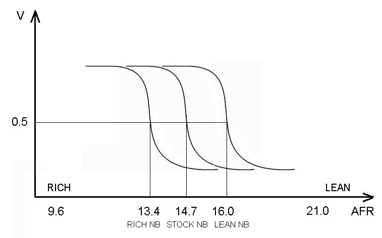
Below is a chart of three lambda sensor voltage transfer curves if you start on the left, you see the voltage is high, about 800 mV. Then as you lean out the mixture, there are three different lambda switching points. The middle line at 14.7:1 corresponds to a stock narrowband sensor. The line on the left is an LC-1 programmed to a mixture that is 9% richer at 13.4:1. The line on the far right is 9% leaner at 16:1. Notice that the voltages are all the same, just shifted for oxygen content in the exhaust.
So when you install an LC-1 or something like it, you are moving the center 14.7 line to the left by a few percent. The Motronic converges on that new line (just as it did to the 14.7 line) but to converge on the line shifted to the left, the Motronic had to add fuel to all the closed loop cells.
Then through the process of adaptation the Motronic averages the fuel added to the closed loop area and applies that added fuel to Open Loop. The Mixture Adaptation process was designed to keep fueling working right for the cat as the engine aged. For lambda shifting with the LC-2 or AF-XIED we have put this Motronic capability to another use!
The combination of lambda-shifting and chip reprogramming could be a powerful pair. We just need John to get his head around this new idea!
cele0001
Registered user
I get what Roger is doing and I get what John is doing.
If you allow the ME to run in open loop mode and change the setting in the fuel map you will accomplish the same thing.
For example:
If we have 20ms injector pulse and want 22ms we can either:
Write 22ms in the table at the location desired (John) or
Manipulate the O2 sensor signal artificially lean to push the ME into adding additional 2ms of injector duration, in the attempt to reach lambda = 1 which is no longer 1 but 0.90 or whatever value.(Roger)
At the end the result is the same.
Except, I agree, in order to accomplish this in some areas of the map you must "turn off" closed loop.
I still think if done right mapping is a much more elegant way to accomplish the task of changing the mixture.
As far as ignition tables go there is no contest.
Roger 04 RT
Registered user
Cele, I think you do see it, but in turning off closed loop (if that is even possible on the 1150), you give up the Motronic's and BMSK's most powerful capability--adapting to long term changes in the engine and to short term changes in fueling content (stoichiometry). I see open loop solutions as very in-elegant for a daily rider.
That's why I say:
Stage 1 is a 4% lambda-shift. The engine runs smoother
Stage 2 is a 6-8% lambda shift, more torque and HP and some spark advance that accrues due to richer mixtures burning faster. Most riders are wowwed! at this point.
Stage 4 is a chip with fine tuned timing plus stage 2
Stage 5 is a chip that has all the previous stages plus fixes specific weak spots in the part of the fueling map not covered by closed loop.
That's my definition of elegant.
............................
That's why I say:
Stage 1 is a 4% lambda-shift. The engine runs smoother
Stage 2 is a 6-8% lambda shift, more torque and HP and some spark advance that accrues due to richer mixtures burning faster. Most riders are wowwed! at this point.
Stage 4 is a chip with fine tuned timing plus stage 2
Stage 5 is a chip that has all the previous stages plus fixes specific weak spots in the part of the fueling map not covered by closed loop.
That's my definition of elegant.
I completely agree to this separation, gradual increments of STAGES !
STAGE 1-3 : For stock or a mod bike with K/N filter and aftermarket exhaust (with cat), just correct the AFR.
STAGE 4 : For stock or a mod bike with K/N filter and aftermarket exhaust (with cat), just correct the AFR, with a little high timing advance (+5-8%) depending of octane petrol use.
STAGE 5 : For de-cat systems ecxhaust, free air filter, or camshafts or any else hardware modification.
Correct the AFR, variable much richer AFR (13,2:1 until 12,5:1) at high revs of rpm (5.700-8100+), rpm limit at 8.100+, with a very high timing advance (+8-13%) for 95+ octane petrol use. (Also the stage 5 chip can work to a stock bike, by little less fuel for protection of catalytic converter).
I make too a super mod chip, it is for special running, for circuit or for bikers enjoy. Needed only a free K/N air filter and de-cat exhaust and use 98+ octane petrols.
Full torque and power at iddle until red line (8100+ rpm) !! The AFR is 13,8 at middle, 13,2-12,4 at high revs, and the timing advance is faster 10-18%, works without pings by 98-100 octane petrols. Has and little more (special) modification at timing of spark map and at at fuel timing of injectors.
All these chip can working by better consumption than stock chip (-5, -8%), except super mod chip (+10%).
Butchpro
Registered user
My five cents...
John, please, look on this article.
It looks like there is no lambda correction possibility. The same conclusion I made earlier based on narrowband lamba sensor principle of work. It is not adjustible, becouse it is simple "yes/no" trigger with only one "point of equilibrium" at 14.7:1.
So the "lamba correction maps" you found are something other, and for success remaping we should understand what they are. And without clear understanding it is potentially harmfull. The best and the hardest way is to disasseble the Motronic firmware, but it is work for months, not for days.
Also as Roger pointed it is useless to modify closed loop fuel cells in maps due to bmw motronic adaptation process. It will work only during first kms after reseting, and then rewriting to 14.7:1.
But for our happy the close loop is less then 1/4 cells in the maps, and we usually need more power for acceleration or fast riding at high revs which is open loop. So your work is really great.
Moreover I believe that closed loop is a good idea for a lot of purposes, because it is engine control feedback. LN1 is good device with good possibilities, but also with expencive price. For better bike perfomance in closed loop (important for instance for the slow city riding) we should think about other lowbudget hardware solution for narrowband lambda sensor, which can shift its "equilibrium point" for a bit richer mixture. May be it is constant shift, not variable like in LC1.
Roger 04 RT
Registered user
Here is a sixth cent ...
Because there are many cells in the fuel map for small throttle angles, my estimate is that about half the fuel cells in the Motronic are covered by closed loop operation--most rpms for throttle angles less than 22 degrees. Here are the rpms vs TPS for a local & highway ride which is typical. Most of the time even when you're accelerating it is from one closed loop cell to another.

Because there are many cells in the fuel map for small throttle angles, my estimate is that about half the fuel cells in the Motronic are covered by closed loop operation--most rpms for throttle angles less than 22 degrees. Here are the rpms vs TPS for a local & highway ride which is typical. Most of the time even when you're accelerating it is from one closed loop cell to another.
My five cents...
John, please, look on this article.
It looks like there is no lambda correction possibility. The same conclusion I made earlier based on narrowband lamba sensor principle of work. It is not adjustible, becouse it is simple "yes/no" trigger with only one "point of equilibrium" at 14.7:1.................
I read this, thanks. I know that the R1150 twin has improve stock maps from single spark. Also by r1150 twin chip can by CCP change easy the maps for more power. Just refit the CCP 30 87 and connect 30 87 87a, but there is still a surge at 2k-3k rpms.
I was resolve this surge to R1150 by improvement to accelerator maps, just i gives more fuel. Also the (stock) advance by little position (0-20%) of throttle is too high, i correct it. See at the previous (Roger's and mine) Charts, the advance (by little position TPS) is too high, so by lean fuel there is a surge. By correction of both map (injection accelerator and timing advance) there is no surge now.
BMW made these maps from 2000-2003 for Euro-3 emission standards. Too high advane at little throttle position by very lean fuel.
At year 2004 BMW stop use the Motronic 2.4 and begins use to R1200GS the Bosch BMSK ME9.
At 2006 year BMW stop use the BMSK and now use the Bosch BMSKP ECU to all models (650-700-800-1200 GS R,RT,S,K,LC...) for emission standard EURO 4 & 5.
Anyway, you sould try a stage 4 chip, you will see the improve..

The Motronic has no such capability to run Closed Loop at anything other than the switching point of the oxygen sensor, which for a stock O2 sensor is lambda=1, which is 14.7:1 for gasoline.
I really can't imagine where you came up with the idea that Closed Loop lambda could be reprogrammed inside the chip of the Motronic. There is no Motronic documentation of this feature. There is no mechanism by which such a feature could work from inside the Motronic. There are no descriptions of a Motronic capability anything like this, anywhere on the web.
Those tables you are re-writing, that you think set Closed Loop AFR, have entirely different functions in the Motronic. It would be best if you didn't modify them until you can document the function.
Please add a link to an article which explains that the Motronic has this capability and how it works ... if you have one show us.
Roger.
I think you 're rigth. I have problem to one R1150, after 300 miles the AFR at close loop is agains lean. Not to all R1150..
A solution for this is to disable the value in map (enable/disable lambda), but i do not want to disable lambda, because i believe that by lambda function the consumption is better.
Can you explain easy how you resolve this by LC-1 ?
What about after few miles when you gives more fuel at close loop ?
Please do not show much charts, explain to me simply, i want to gather a lot of information (from you and many other friends involved on "remaping") and at monday i hope find a solution to the issue.
Butchpro
Registered user
No words in my post were about timing advance.
Of course it is useful and it works.
By the way I believe if bmw bikes had close loop by knock sensor, it would be great. But they have not ...
Also I found that one team in Russia successfully disassembled the firmware for VW Mono Motronic 1.3 (looks very similar to BMW, the same Siemens chip, the same EPROM). They do not say much about it, it is commercial project.
If they have done, may be I try... Tomorrow I will try to download my R1200C firmware.
cele0001
Registered user
I seriously doubt there is any firmware on the EPROM. There should only be data (maps) on that chip.
Engine management is one of the Boschs's big income drivers and they go through great lengths to protect their investment.
I would go as as far saying that the main micro controller is custom (based on something, but custom built with firmware already on it for Bosch).
Otherwise it would only take a couple of days of effort to obtain the operating system.
But I could be wrong. I have been out of the game.
Roger 04 RT
Registered user
Roger.
I think you 're rigth. I have problem to one R1150, after 300 miles the AFR at close loop is agains lean. Not to all R1150..
A solution for this is to disable the value in map (enable/disable lambda), but i do not want to disable lambda, because i believe that by lambda function the consumption is better.
Can you explain easy how you resolve this by LC-1 ?
What about after few miles when you gives more fuel at close loop ?
Please do not show much charts, explain to me simply, i want to gather a lot of information (from you and many other friends involved on "remaping") and at monday i hope find a solution to the issue.
It is very simple. Two ways:
1) Bosch LSU 4.2 in place of stock sensor. Connects to LC-1 programmed to desired AFR. LC-1 analog output connects to Motronic O2 input. Done. AFR shift is permanent in closed loop area directly. AFR shift migrates to Open Loop area through mixture adaptation.
2) Stock Narrowband sensor to AF-XIED. AFXIED set to 13.8-14.1. Connect AFXIED to Motronic o2 input. Same results as #1.

Similar threads
- Replies
- 8
- Views
- 2,362