

You are using an out of date browser. It may not display this or other websites correctly.
You should upgrade or use an alternative browser.
You should upgrade or use an alternative browser.
LED rear light circuit diagram
- Thread starter brassmonkey001
- Start date
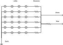
The single resistor in the 'sidelight' feed needs to be chosen with care and will need to be a higher wattage rating and of different value to the other resistors. (its doing a different job). You may need to use blocking diodes in the 2 feeds
Or a simpler solution would be to put a diode in circuit so that when the sidelights are required only a few of the LEDs light up but all of them do when the brakelight is required and get rid of the resistor in sidelight feed
D6
Registered user
It would be better to separate the brake circuit from the side circuit, why not have 50% of the LED's for the side circuit and the rest for the brake.
Don't think you can get LED's that are dual brightness.
yes you can,,, commonly used,,,have em in mine, the little square uns, 4 terminals

DollyRocket
Registered user
When you say it wont work - what have you done to test it? have you mocked it up on a bit of breadboard for testing?
I agree with the comments above - I would completely separate the brake and tail circuits. Your LED's do not show the polarity in your diagram, Just confirm that the contacts in the bulb holder aren't the wrong way around (shouldn't be otherwise you would end up earthing through the other circuit filament)
If you have ABS you will need to simulate the current drawn by a bulb as the ABS ECU monitors the brake light circuit - hence you may need a power resistor in parallel with the brake circuit (The LED probably wouldn't be able to pass enough current (I think the bulbs are 30W - ish)
You can buy drop-in replacements in a bulb holder rather than making up your own circuit - Or Nippy Normans has a sale on with LED tail lights for 1150GS's (Bought one myself a couple of days back)
See : http://www.lunaraccents.com/LED-taillight-circuit.html
brassmonkey001
I should change this
Thanks for the replies
I don't much like the idea of more LEDs at the same brightness. I want two levels of brightness like you get with normal rear lights.
I've got a bunch of those kicking around, how do you get two levels of brightness out of them?
When I say it won't work, what I mean is I know without building it that it will not perform as I want it to and I want to know how to fix it.
I don't want to buy one already built, I have the necessary bits and the capability to make one myself for a good bit cheaper, I just lack the knowledge to fill in the details.
Thanks for the link BTW, most illuminating, ho ho.
I would also like this thread to be useful to others who would like to make their own LED board.
It would be better to separate the brake circuit from the side circuit, why not have 50% of the LED's for the side circuit and the rest for the brake.
Don't think you can get LED's that are dual brightness.
Or a simpler solution would be to put a diode in circuit so that when the sidelights are required only a few of the LEDs light up but all of them do when the brakelight is required and get rid of the resistor in sidelight feed
I don't much like the idea of more LEDs at the same brightness. I want two levels of brightness like you get with normal rear lights.
yes you can,,, commonly used,,,have em in mine, the little square uns, 4 terminals
I've got a bunch of those kicking around, how do you get two levels of brightness out of them?
When you say it wont work - what have you done to test it? have you mocked it up on a bit of breadboard for testing?
I agree with the comments above - I would completely separate the brake and tail circuits. Your LED's do not show the polarity in your diagram, Just confirm that the contacts in the bulb holder aren't the wrong way around (shouldn't be otherwise you would end up earthing through the other circuit filament)
If you have ABS you will need to simulate the current drawn by a bulb as the ABS ECU monitors the brake light circuit - hence you may need a power resistor in parallel with the brake circuit (The LED probably wouldn't be able to pass enough current (I think the bulbs are 30W - ish)
You can buy drop-in replacements in a bulb holder rather than making up your own circuit - Or Nippy Normans has a sale on with LED tail lights for 1150GS's (Bought one myself a couple of days back)
See : http://www.lunaraccents.com/LED-taillight-circuit.html
When I say it won't work, what I mean is I know without building it that it will not perform as I want it to and I want to know how to fix it.
I don't want to buy one already built, I have the necessary bits and the capability to make one myself for a good bit cheaper, I just lack the knowledge to fill in the details.
Thanks for the link BTW, most illuminating, ho ho.
I would also like this thread to be useful to others who would like to make their own LED board.
ahebron
Registered user
I have built 2 side light indicator bullet lights for a 1935 Lagonda Rapier. I used 5 x 10mm 125,000mcd white LEDs. To control them I have fed with the indicator through a diode (drops 1 volt) at full voltage. The side light circuit again through a diode then into 7805 voltage regulator which drops voltage to 5 volts. All leds are fed by both supplies So we then have the indicators running at 12 volts which overrides the side lights at 5 volts when used. Even running at 5 volts the light is brighter than the old 12 volt 5 watt globe that used to fitted.
Hope that all makes sense.
Adrian
Hope that all makes sense.
Adrian
yes you can,,, commonly used,,,have em in mine, the little square uns, 4 terminals
What do you connect to the 4 terminals?
DollyRocket
Registered user
New link : http://www.redcircuits.com/Page85.htm
Nice solution to your problem, you can vary the resistor values to change the bias on the transistor and hence brightness.
Nice solution to your problem, you can vary the resistor values to change the bias on the transistor and hence brightness.
D6
Registered user
What do you connect to the 4 terminals?
i dunno, i jus know this because i replaced some , cos of water ingress,
TECHNO supplied em, i presume they work like a dual filament bulb but with an earth for each filament?
i just spun em round in the holes till they worked, then soldered em in,sorry
a look at the back of the board would answer that, ill look tomorrow
Automods
Guest
Hi Guys I know this is an older post but if this has not been sorted out let me know as I have a VERY simple soloution. I do this for a living and will be happy to help.
The reason your Schematic has partly failed is because you are linking the Brake and Rear light together, But more importantly is, if your lights are off, and you put your brakes on the power will go back through the wiring and will power your front lights too.
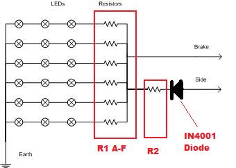
Keep your LEDs in 3s they are easier to control the brightness, I have edited your schematic but without the spec of your LEDs I can not tell you what size resistors to use, give me this info and i'll tell you the exact resistor size you need.
The Diode in that position will stop the brake light interfering with your normal lights.
The reason your Schematic has partly failed is because you are linking the Brake and Rear light together, But more importantly is, if your lights are off, and you put your brakes on the power will go back through the wiring and will power your front lights too.
Keep your LEDs in 3s they are easier to control the brightness, I have edited your schematic but without the spec of your LEDs I can not tell you what size resistors to use, give me this info and i'll tell you the exact resistor size you need.
The Diode in that position will stop the brake light interfering with your normal lights.
brassmonkey001
I should change this
Hi Guys I know this is an older post but if this has not been sorted out let me know as I have a VERY simple soloution. I do this for a living and will be happy to help.
The reason your Schematic has partly failed is because you are linking the Brake and Rear light together, But more importantly is, if your lights are off, and you put your brakes on the power will go back through the wiring and will power your front lights too.
Keep your LEDs in 3s they are easier to control the brightness, I have edited your schematic but without the spec of your LEDs I can not tell you what size resistors to use, give me this info and i'll tell you the exact resistor size you need.
The Diode in that position will stop the brake light interfering with your normal lights.
Nice one fella.

I'll dig out the LEDs and get back to you on the spec.

brassmonkey001
I should change this
Gosh, where are my manners?
Welcome to the site, Automods.
Welcome to the site, Automods.
brassmonkey001
I should change this
OK, the LEDs I have are 3000 mcd, wavelength 620-630nm, Vf(V) 2.2 - max 2.8.
Which means very little to me. So what resistors will I need?
Which means very little to me. So what resistors will I need?
The forward voltage (Vf) is somewhere between 2.2 and 2.8 volts. So, taking 2.5 volts as the middle and a current required of 30milliamps. the data sheet should say what current is required, but it's usually around 20 to 50 milliamps(mA)
When your bikes running, you're generating around 14 volts.
So you need to drop 11.5 volts across the resistor while 30 mA is running through it.
r = V/I
r= 11.5/.03
r= 383.33 ohms.
You can't buy that value, so you need to look up an E24 series equavalent, which could be 390 ohms.
One thing you need to consider is the power dissipated.
Power = volts * amps
P= 11.5 * .03 = .345 W - not a lot.
This is all for one resistor and one LED. I don't know what circuit you settled on, but the maths is easy - perhaps you could post your homework and we'll make it?")
When your bikes running, you're generating around 14 volts.
So you need to drop 11.5 volts across the resistor while 30 mA is running through it.
r = V/I
r= 11.5/.03
r= 383.33 ohms.
You can't buy that value, so you need to look up an E24 series equavalent, which could be 390 ohms.
One thing you need to consider is the power dissipated.
Power = volts * amps
P= 11.5 * .03 = .345 W - not a lot.
This is all for one resistor and one LED. I don't know what circuit you settled on, but the maths is easy - perhaps you could post your homework and we'll make it?

Similar threads
- Replies
- 1
- Views
- 1,036