After some time away from home I booked a day off work and headed to the workshop.
The challenge is the compound angle. In plan the driveshaft angle needs to set over to centre the wheel. Then in elevation I want to use the UJ nearest the final drive to pitch the drive downward to help match the front without severe angle for the gearbox UJ.
Because I'm changing virtually everything the only reference point is the width of the swingarm which is set by the jig.
This is going to take a bit of trial and error.
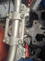
From some 90mm SHS I can make a mating flange to suit the 37/11 K75 FD. Its a trapezium just to make life easier and the bolting centres are not on a PCD. Thanks for that BMW.
Using some paper I make a template that I can transfer to the SHS. 2x 10mm, 2x 12mm holes and one 70mm hole later (via trip to screwfix for a 70mm hole saw) I have a mating connection to the FD. It needs some fettling to fit but its close enough for now. A healthy dose of beautification is also required but I just need something that works dimensionally at the moment

Splitting the top face then grooving the bottom face I can bend the flange faces to 13 degrees outward (circa 50% of the max UJ range) then infill the gap with flat bar and weld up the grove. That takes care of one angle (the downward pitch). This puts the angle change pretty much on the centre of the FD UJ.
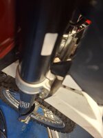
I can now start to mock up the shaft tunnel using the eyechrometer. The shaft tube is 76x3mm ERW tube. I don't like using ERW but there wasn't any CDS seamless in the size I wanted. Now to cut a hole in the side of the tube to accomodate the swingarm bearing carrier I trimmed up in the lathe.
Another trip to screwfix with the dog and I have a 44mm hole saw leaving in me a few mm of fettling with the file for a snug fit for the 46mm OD bearing carrier.
This is where the fun begins; the offset angle. I marked the long swing arm piece with the measurement for the face of the wheel and the centre of the frame. With a spare 1150gs hub bolted to the K75 FD I can hold the hub vertical, perpendicular to the swing arm bolt centre lines and correctly offset.
Glad I took the time to build that jig frame.
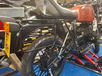
All tacked together will a couple of little braces I can try it on the bike.

I am feeling happy its coming together.
I plan on being able to run 150/17R and 110/19F 1150 wheels as well as 21/18 tubeless rims. So I use the 150/17 for test purposes.
A quick lash up of sub frame and seat I can cycle the swing arm through what will be full droop and near full compression (I'm aiming for +/- 15 degrees)


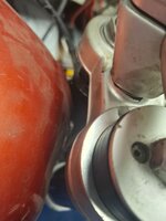
I can test the shock position too, it's a bit tight to the swing arm and the shock. I do want to use this type of shock configuration as it reduces the amount of various forces the swing arm has to deal with.

This has allowed a very important measurement to be taken..... free float on the FD UJ
I have 12mm of free movement at horizontal. So this allows me to trim the driveshaft tunnel down to length. I need to do some research on how much free float to leave.
12.76 degrees of upward swing before I hit the subframe.
Now then......weight!
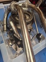
As much as I would love to build this swing arm out of Ali that is well beyond my metal gluing skills so having chosen steel you are no doubt thinking it'll be a boat anchor hanging off the back with horrendous unsprung mass.
Well an LWB twinshock swingarm with driveshaft, final drive and brake shoes (no fluid) weighs approx 12kg
My swing arm in its current form, with K75 FD, oil head drive shaft, no fluid and no brake caliper....11kg.
There is obviously a lot of metal and weld still to go on but that big hunk of 90x5 SHS also needs a lot of trimming down. I was fearing I'd be closer to 15kg at this point. This may actually work.