Auxiliary fuse box

MikeO

Well-known member
UKGSer Subscriber
Joined
May 31, 2002
Messages
12,410
Reaction score
982
Location
Dereham, Norfolk, today...
Hi all,

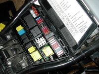
I've decided to tidy up some of the spaghetti wiring and randomly placed in line fuses on the Adv. To this end I have bought an eight gang fuse box...

i-7kNcnfB-L.jpg


I haven't worked out exactly where it is going to live yet (although it'll probably either be on a metal plate on top of the air cleaner, or in the space where the servo resided), but I want all the power going to it to be ignition switched. The fuses will be for LED spots & fogs, heated seats, heated clothing and horn (amongst other things) - no huge power draw - and I'll use the appropriate fuse for each circuit.

I have a switched supply that I can use to fire a suitable relay, but my question is - how do I supply power to all eight 'input' side spade connectors?

i-8Jk62nB-L.jpg


There must be a more elegant way than looping spade connectors with two wires each along the row - any thoughts?

Cheers,

Mike :cool:
 
The design of your fuse box leaves little option that to loop a series of lives x8

The other alternative is a common bus fuse box such as this

 
Just some neat crimping needed Mike. :thumb2

Can't find a pic of the ones I've done before, but done neatly, they are tidy enough :nenau


On this version, there are inputs from a permanent live on one end, and a set of ignition/relay supplied lives on the other end.


FuseBlock9.jpg
 
Just some neat crimping needed Mike. :thumb2

Can't find a pic of the ones I've done before, but done neatly, they are tidy enough :nenau


On this version, there are inputs from a permanent live on one end, and a set of ignition/relay supplied lives on the other end.


FuseBlock9.jpg

That's what I thought I'd end up doing.

I doubt mine will look that neat... :D

Mike :cool:
 
This may give you some idea

. http://edelweiss.smugmug.com/Motorc...re-Blue/2787815_PhBnck#!i=185607288&k=BTwF57t

Click on the pictures for the text to be displayed.


If you want to use the one you show in your picture, then to solder a thick wire along the tags is the neatest way, the challenging bit will be to insulate the tags.

Are those pictures of your bike warm shed? Do you know what model number that fuse block is?

The plate looks the same as the one Motorworks do...

Mike :cool:
 
This is a picture of my fuse box layout.

Alot of people are probably unaware that the fuse box is designed to take a second bank of fuses. The plastic fuse holders in my layout are identical. I sourced my second one from a scrap loom I had.

However, if the fuse box is designed for a second fuse bank then it might be that they are available to specialist companies who deal in the modification of the bikes for the emergency services.

I also utilised the relay mounts from the scrap loom for my Spot light relay.

Just keeps all the electrics control and protection neat and tidy in the proper place.
 

Attachments

  • R1150Gs Fuse Box Edited.jpg
    R1150Gs Fuse Box Edited.jpg
    77.3 KB · Views: 692
This is a picture of my fuse box layout.

Alot of people are probably unaware that the fuse box is designed to take a second bank of fuses. The plastic fuse holders in my layout are identical. I sourced my second one from a scrap loom I had.

However, if the fuse box is designed for a second fuse bank then it might be that they are available to specialist companies who deal in the modification of the bikes for the emergency services.

I also utilised the relay mounts from the scrap loom for my Spot light relay.

Just keeps all the electrics control and protection neat and tidy in the proper place.

:bow:bow
 
i-HXRTZMS-L.jpg


This will do for now I think - if it proves troublesome then I'll rethink and refit next winter...

Many thanks for all the input...

Mike :thumb2

EDIT - and look out for a scrap loom to replicate what Ian has done - excellent work... :cool:
 
There's another easy way to add a fused circuit with minimal pissing about.....one of these :

3-XL.jpg


Full write up of them HERE :thumb2
 
There's another easy way to add a fused circuit with minimal pissing about.....one of these :

3-XL.jpg


Full write up of them HERE :thumb2

Hi Bill,

Yes, I remember reading that - a very neat gizmo. I've already got good access to switched power - this is all tidying up really...

Mike :thumb2
 
Don't build in more trouble

All these nasty crimp connectors are just too much! A motorcycle, being exposed to the elements, is no place for such things. If you must use crimp on connectors at least use those made with heat shrink covers. Using the cheap type is just asking for trouble as moisture can and does get in all too easily.

John
 
Are those pictures of your bike warm shed? Do you know what model number that fuse block is?

The plate looks the same as the one Motorworks do...

Mike :cool:

No its not my bike, its from the Eidelweiss website, http://edelweiss.smugmug.com/Motorcycles

though I do have a 2005 1150GSA in silver just like him. The place at the front of the seat seems to be an ideal location. I like the mounting plate( in the "technical Stuff" section) he uses for the Givi box, might copy that, Ive just sources the stainless plate.
 
All these nasty crimp connectors are just too much! A motorcycle, being exposed to the elements, is no place for such things. If you must use crimp on connectors at least use those made with heat shrink covers. Using the cheap type is just asking for trouble as moisture can and does get in all too easily.

John

I'll agree to differ with you here John.

None of the OEM switches or connections on my BMW are waterproof and sealing moisture in by overuse of heatshrink is asking for more corrosion than letting the elements get to it. Accept that water will get in and give it a way to get out is the best thing in my experience...

Mike :cool:
 
If you are careful you can cross drill one side of the fuse box and insert a couple of pieces of solid twin and earth cable, through all the terminals. A bit of soldering connects it all up securely. This what I did when I replaced the completely rotten fusebox on my TDM 850 MK1 (and again on the secondary fuse box you can see in the final picture). I did the same as Ian on my R1100GS, and fitted a second bank of fuses, in the existing fusebox, like him I got my fuse module from a scrap loom.

fusebox1.jpg


fusebox2.jpg


fusebox3.jpg


fusebox4.jpg


fusebox6.jpg


fusebox5.jpg
 
I'll agree to differ with you here John.

None of the OEM switches or connections on my BMW are waterproof and sealing moisture in by overuse of heatshrink is asking for more corrosion than letting the elements get to it. Accept that water will get in and give it a way to get out is the best thing in my experience...

Mike :cool:

Happy to differ! The crimp on connectors shown don't always allow the moisture to come out though. A proper shrink fit connector will not only keep the moisture out but will also add considerably to the mechanical strength at the point where the cable enters the connector. In my professionally life we never used simple crimp on connectors. As I have said before I ran a garage repairing Citroen cars. Citroen themselves banned the use of simple crimp on connectors in the 1990s because of problems caused by corrosion especially once on board computers became common.

John
 
I have something similiar but my terminals all come from below, cant remember if I cut the spades off and soldered wires to it or if it came that way :nenau.

Once you cut the mountings off it slid directly into the spare space in the fuse box, looks like it was made to measure :)

Ill try take a pic on Friday as Im planning on working on bike to fit some Goodridge hoses and change the master cylinder piston which Im not looking forward to :blast
 
OK - change of plan.

i-75s5ZvK-L.jpg


I've bought one of these and intend to mount it on one of these from Motorworks:

i-Vt8FMhq-L.png


i-xJKktkM-L.png


Nice design - mostly...

i-7h9W9V4-L.jpg


Nice touch are the LEDs - when a fuse blows, the LED goes out...

i-ZJjPgmt-L.jpg


Single power input (I will run it through a hefty relay - switched power).

i-PrKRKpR-L.jpg


And there's the snag. The input isn't insulated. Wouldn't a better design be to have the lid of the fuse box cover this connection? :confused:

Any ideas on how to properly insulate this connection? I want to avoid a big lump of duct tape... :D

Mike:cool:
 
And there's the snag. The input isn't insulated. Wouldn't a better design be to have the lid of the fuse box cover this connection? :confused:

Any ideas on how to properly insulate this connection? I want to avoid a big lump of duct tape... :D

Mike:cool:

In the same way as your battery's positive terminal is insulated :thumb2


Back
Top Bottom