Dogbytes' R80 ST project

I've been a bit distracted this week but, since the frame is 'nearing' completion, I've been thinking of what to do next and I'm very tempted to put a 50mm extension in the swing-arm.

This was raised further, in my consciousness, as I was repairing a driveshaft for someone else. This driveshaft had been extended in what, I take it, is the accepted method (or one of them) of cutting the shaft, turning spigots on the cut ends and then making an extension with two matching counterbores and, after carefully aligning the whole lot, welding it together. A variation is to use two driveshafts cut to allow assembly of a bit of each to make one of the correct length - this allows the process to be achieved with only one weld instead of two.

I remain to be convinced that either of these is ideal. Although, I suppose, if it works it works. Clearly the ideal method is to have a new driveshaft, of the required length, made from scratch. I don't know how much this would cost but in terms of what people spend having these bikes hand built I don't imagine it would be a deal-breaker.

My idea was to extend my driveshaft using a scarf joint method similar to the way I've done my frame rails but I'm told, by someone who's expertise is beyond reproach, that it won't work. I may have a look round and see if a shaft exists which uses the same UJ but which is over length and big enough that I can cut new splines on the bevel box end...

Anyone got any experience of these or other methods?
 
Back on it

It takes about 3 hours to make a pair of those scarf joints. A bigger mill would speed things up - but then I'd need a bigger workshop and that would cost more so I wouldn't be able to spend as much time doing this...

Can't get over that, very ordinary-looking, HPN on the recent thread. €36k! They must work with a milling machine the same size as mine!
 
Remaining scarf joints made

Just got to put the counterbores in, then I can weld them into the frame tubes. Yes, yes, I'll try up the bolt heads! :)
 

Attachments

  • image.jpg
    image.jpg
    157.8 KB · Views: 866
Scarf joints in

It took a little longer than expected but they're almost in. That is they're all at least partially welded in but I need to strip it down now to make it easier to get all the way roun the tubes. When I assembled it there was quite a lot of 'spring' in the frame which had to be taken up before everything lined up. I noticed that when I cut the tubes and I could have shortened the bottom tubes by 5mm to get rid of it but I thought a bit of tension can't hurt so I've left it there. It'll look nice cleaned up.
 

Attachments

  • image.jpg
    image.jpg
    124.3 KB · Views: 1,299
Getting close!

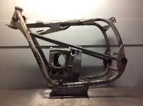
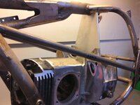
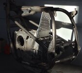
I'm hoping to get my frame finished this week. I have the top engine mount, the foot peg/controls and fairing mounts still to do. Then there's a bit of tidying of bracketry and that's it.

In the meantime, yesterday in fact, I had an emergency repair to do to Pete Keys' extended driveshaft. There are, of course, two welds on driveshafts extended in this way and I'd re-done one of them a few weeks ago, after it snapped. Imagine my delight then, when he told me it had snapped again and it turned out to be the remaining example of the other person's welding and not mine. That means my welding is better than at least one other person's!

Pics below show:

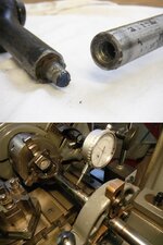
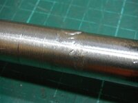
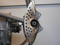
The broken shaft - you can see how shallow the weld depth is.

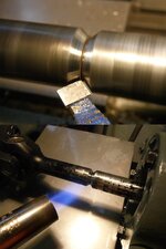
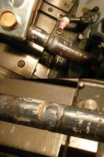
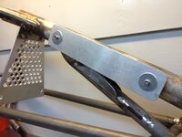
The shaft assembled in the lathe and straightened. Checking with a dial gauge shows I can get it to within about 0.2mm. After that the surface quality of the, previously welded, shaft starts to intrude on accurate measurement.

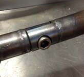
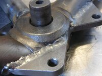
The join V-ed out. Nice and deep this time.

Pre-heating avoids cracking of the first fusion pass.

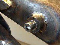
The first pass of TIG welding - fusion only, no filler.

The filler pass. Nice big rod, all done in one hit.

A quick skim on the lathe to take off most of the excess filler - no room in the swing-arm to leave it on.

It was then lightly polished but I forgot to take a pic of the finished article.

Of course the downside is that next time it breaks itll definitely be one of my welds! :)
 

Attachments

  • 001.jpg
    001.jpg
    105.9 KB · Views: 932
  • DSCF5744.jpg
    DSCF5744.jpg
    85.5 KB · Views: 946
  • DSCF5746.jpg
    DSCF5746.jpg
    107.4 KB · Views: 937
  • DSCF5753.jpg
    DSCF5753.jpg
    41 KB · Views: 947
Final bit of bracing. Seriously, no more!

Just beginning to look at making the alu plate upper engine brace.
 

Attachments

  • image.jpg
    image.jpg
    124.9 KB · Views: 911
A lot of holes!

It's going to look like this. I'll finish off the bracket and weld it to the frame tomorrow.
 

Attachments

  • image.jpg
    image.jpg
    197.6 KB · Views: 887
For some reason I can only submit one pic at a time via iPad

Pretty - and I can have grated cheese in the workshop now!
 

Attachments

  • image.jpg
    image.jpg
    155.8 KB · Views: 873
Lugs for the rear sets...

The lugs for the attachment of the rear-sets to the frame are 1/4" plate. I'm going to make the controls because I want a very plain, functional style rather than the CNC carved alloy which are all that seem to be available commercially. The positioning of the controls themselves will have to co-ordinate with those of the seat and handlebars. Because my K1200 S is so comfortable I'll probably plot the contact points of that bike (or, more likely,one with the HP / Gilles Engineering footrests because they're even better) and transfer them to this project.
 

Attachments

  • DSCF5767.jpg
    DSCF5767.jpg
    116.1 KB · Views: 814
  • DSCF5769.jpg
    DSCF5769.jpg
    99 KB · Views: 817
  • DSCF5776.jpg
    DSCF5776.jpg
    107.1 KB · Views: 819
  • DSCF5779.jpg
    DSCF5779.jpg
    83.1 KB · Views: 815
Fittings for the engine electrics

I've made a couple of threaded bosses and TIG-ed them into the spine tube. These will hold the aluminium plate which carries the coils, etc.

There are a few welds to finish off (needed the motor in to position things and couldn't get round the back of them with said motor in the way...) and the fairing mounts to make and then the main frame cradle is done! This will be a major psychological boost as I can then begin putting stuff back on it instead of taking bits off! :)
 

Attachments

  • El.Plate.JPG
    El.Plate.JPG
    123.3 KB · Views: 782
  • El.Boss.JPG
    El.Boss.JPG
    104.6 KB · Views: 779
It's never straightforward...

Offering up the fairing today, to see where the various mounts are going to go, it transpires that the 24 litre tank is too wide at the front. That being so, I now have a 24 litre Bumble-Bee colour scheme tank to get rid of and a smaller one to obtain. Any offers? I'll post some pics later. It's not the best tank in the world but it isn't the worst either. I don't know if the paint is original so I don't know what's under it. There is a small pinhole at the back of it which I'll probably weld up unless someone wants desperately to do it themselves...
 

Similar threads


Back
Top Bottom