Dogbytes' R80 ST project

I'm guessing that the inserts slide back out of the way internally allowing the tubes to be released?

No, it's much simpler than that. :)

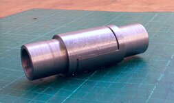
If you look at the pic of the of the partially-machined bits, the reduced portion slides into the tube ends and is welded in position. The full-diameter portion will be machined so that only half of it remains and that will fit to its matching component in, what I believe woodworkers call, a Scarf joint. One half of the Scarf joint will have a clearance hole and its opposite number a tapped hole - so that a screw can fasten them together.
 
I'm guessing that the inserts slide back out of the way internally allowing the tubes to be released?

Very interesting thread :thumb2

Mr Tunneruk, if you look at MikeOs thread on engine bars (where they join), you will see how he is probably going to do it.... maybe.
 
Got it. I remember chatting some years ago to Brian Chapman who'd built one of the fastest Vincent 500 and 1000 dragbikes ('Mighty Mouse'). Don Godden built the spindly frame and because Brian had to transport the bike in his Transit, the frame tubes had scarf joints this side of the head stock to allow the frame to be seperated. Wonderfully simple.:thumb2
 
Got it. I remember chatting some years ago to Brian Chapman who'd built one of the fastest Vincent 500 and 1000 dragbikes ('Mighty Mouse'). Don Godden built the spindly frame and because Brian had to transport the bike in his Transit, the frame tubes had scarf joints this side of the head stock to allow the frame to be seperated. Wonderfully simple.:thumb2

I was never lucky enough to see 'Mighty Mouse' in the metal but I remember when it was racing (and winning). It is a bike I keep in mind. Simple, light and beautifully executed. If I could build something even remotely as good as that I'd be a very happy man! Maybe if I practice more...
 
Here's Brian Chapman's 'Mighty Mouse'. He also built a 1000cc version later. You can just make out the tiny scarf joints halfway along the top tubes.
 

Attachments

  • mighty_mouse_3.jpg
    mighty_mouse_3.jpg
    68.6 KB · Views: 979
Here's Brian Chapman's 'Mighty Mouse'. He also built a 1000cc version later. You can just make out the tiny scarf joints halfway along the top tubes.

Superb. There are some clever b*****s about! :) There have been some amazing bikes built over the years.

I do sometimes wonder why I think I can do it better than BMW! I suppose I'm just curious to see how it turns out - and I have the luxury of it being my hobby so it doesn't have to go out there and win a damned thing ;)
 
Not bad for a chippy :D

I'll tell Brian when I see him next, he'll be chuffed.
He still rides all year round, and still on Vincents :thumb2
 
Not bad for a chippy :D

I'll tell Brian when I see him next, he'll be chuffed.
He still rides all year round, and still on Vincents :thumb2

That's great to hear. He (or at least Mighty Mouse) was at his peak in about 1976 when I first started riding. Fastest single cylinder drag bike in the world. High eight second runs, as I recall. Used to read about him in MCN. A living legend, long may he ride. :)

Hey, imagine what he could have achieved with an airhead motor!!! :D
 
Not bad for a chippy :D

I'll tell Brian when I see him next, he'll be chuffed.
He still rides all year round, and still on Vincents :thumb2

I am pleased to hear that as I'd heard that he'd passed away. It was at some motorcycle show many years ago we chatted. After 45mins I thought he might be getting a bit bored but not at all. A pleasant modest chap. So how well did his 1000cc bike compared to 'Mighty Mouse'. I believe it might have been an ex-George Brown motor.

The frame, as I said before, was built by Don Godden's company in nearby East Malling. He passed away last year.

Whilst on the subject of sprinting/drag racing, I remember seeing Fred Cooper sprint his bike along the Ramsgate Esplanade when I was a lat. He had a small shop in Greenwich and when restoring a Royal Enfield Constellation, I took the magneto to him to refurbish. I took all of my Ramsgate photos to show him, and which he seemed to enjoy. We got chatting about the George Brown v Alf Hagon 'battle' to break the 10 second barrier, which Hagon eventually succeeded in doing first. Old Fred smerked as he believed Hagon's breaking of the barrier was a bit of gamesmanship.
 
Just need to drill and tap. And machine the rest of them...
 

Attachments

  • image.jpg
    image.jpg
    106.6 KB · Views: 938
Fitted but not yet welded in - and I still haven't managed to machine the flats on the other ones...
 

Attachments

  • image.jpg
    image.jpg
    185.8 KB · Views: 889
Fitted but not yet welded in - and I still haven't managed to machine the flats on the other ones...

Looks like a nice job, will you be welding them in at that position? If so Is there a reason that you're not orientating the flats to be horizontal in order it bears the weight rathe than the sheer forces of the bolt strength? (I have no idea if that makes sense :blast)

Are you not tempted to weld them in at 90 degrees to where they are now? (That's what I'm getting at :D)
 
Sort of think that the Allen bolt head needs to be curved to match the contours :D
Maybe a button head would suit:nenau

It will have a modified fastener to make it a little neater. That was the only type of M12 I had in the workshop.

Or perhaps I could just use those ones but engrave the bits that show and gold-plate them! :)
 
Looks like a nice job, will you be welding them in at that position? If so Is there a reason that you're not orientating the flats to be horizontal in order it bears the weight rathe than the sheer forces of the bolt strength? (I have no idea if that makes sense :blast)

Are you not tempted to weld them in at 90 degrees to where they are now? (That's what I'm getting at :D)

They will be welded in position because at the moment they're just an interference fit. And they will be orientated as shown. For the flat to bear any weight in the way (I think) you suggest, would make the whole thing difficult to drop out - I'd have to shift it sideways first. I did consider fitting them with a hollow spigot going all the way across with a bolt to hold it all together but it would have compromised the strength of the scarf joint components and would have been unsightly due to its bulk. The fact is that it doesn't need to be any stronger than it is. The bolts won't be stainless - they'll be a high strength steel alloy so their shear strength will be way more than adequate. Yeah... I'm sure it will... :)
 
They will be welded in position because at the moment they're just an interference fit. And they will be orientated as shown. For the flat to bear any weight in the way (I think) you suggest, would make the whole thing difficult to drop out - I'd have to shift it sideways first. I did consider fitting them with a hollow spigot going all the way across with a bolt to hold it all together but it would have compromised the strength of the scarf joint components and would have been unsightly due to its bulk. The fact is that it doesn't need to be any stronger than it is. The bolts won't be stainless - they'll be a high strength steel alloy so their shear strength will be way more than adequate. Yeah... I'm sure it will... :)

:thumb
 

Similar threads


Back
Top Bottom