Fitting Lights to F650GS

HogHog

Active member
UKGSer Subscriber
Joined
Jun 28, 2012
Messages
246
Reaction score
0
Location
Inverness, Scotland
Hi,

Those of you that know me will know that I'm as thick as a thick thing - those of you that don't should read the first part of the sentence (it's in red to make it easier for you) :D

I have these lights that are nice and bright (unlike me) and I thought I'd try to fit them on my 2008 model F650GS - but I'm too thick to work out how to do it (I did manage to wire them up to a spare battery and that's how I know they're so bright :P)

Can anybody help.?

lights3jpeg_zpsaab0f5ab.jpg


lights1jpeg_zps18ab0010.jpg


lights2jpeg_zpsc18a5c60.jpg
 
HogHog we need more info

Do you just want some help in the wiring or actually how to mount the light units or both?

Itemise and photograph what you have got if you can, have you got any of the "required" items or just two lamps with wires coming out their backs?

Assuming its just the wiring you want advice on..

Would you accept having them independently operated by a separate switch (eg on handlebars or instrument panel). In which case the wiring is easy as you connect the lamps directly to the battery with a fuse and an override switch in that circuit. IF you do it this way, if you switch off the ignition the lamps remain on unless you also flick the override switch, you also have to flick two switches to dip - not so good.

Do you want these lights to come on/off automatically with the high beam as advised in your instructions (not so easy)? In this case you have to do the more complicated option of tapping into the high beam wiring (3 on your diagram above) and using a relay and having an optional override switch.

Are you really just after a wiring diagram for an F650 rather than a car and the best place to tap into the high beam (3)?
 
Thanks for the reply. I'm happy for them to just come on with the normal low-beam headlight if that's not against the law. I only posted the wiring diagram and instructions to show what I bought. I don't think I need them to be linked to High Beam, in fact I think that defeats the purpose as the standard High Beam seems good enough for night riding. I'm just not sure how to wire them as I see threads with "ballast" and "relay" etc in them and that scares me..!!!
 
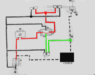
Putting aside whether you should run these lights on low beam -Does this wiring diagram make things any clearer?

Dont be concerned about a relay - it is just a switch which is activated electrically rather than with your thumb. If a current passes along the green wire to terminal 86 on the relay and terminal 85 has a wire to the -ve battery terminal, then the switch is turned ON so completing the circuit in the red wire (across terminals 30 and 87) so the lamps will light up. IF there is no current in the green wire, because the override switch (6) is turned off or the bike ignition switch is turned off, then the default state of the relay switch is OFF, so lamps are off.

In the diagram the solid lines are the wires you have to add - a new circuit from the battery to the lamps which includes a fuse and the relay switch - red lines. You also have to complete the circuit by sending a wire from the lamps back to the battery - black solid lines . You can instead fix the negative wires to the metal frame (ground) shown as the arrow heads with three bars on your original diagram, but in my view it is just as easy to send a wire back to the battery (others might disagree).

The dashed lines are ones that already exist on your bike. What you need to do is splice into the existing wiring (at 3) and run a wire from this point to the relay ( terminal 86) via an isolation switch (6). As mentioned before you then have to run a wire from terminal 85 back to the battery -ve terminal.

The switch (6) shown in diagram has three wires. This is because it assumes you are using an illuminated switch that has a small LED inside it. This is why you need another wire back to the battery -ve terminal to close the LED circuit. IF you dont use an illuminated switch you only use the two green wires

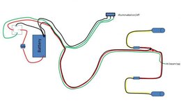
So that is the schematic of the connections that you have to make, now you have to decide where to put these switches, fuse and junctions.

Before you do that do a bench test of this circuit to make sure it works - you may have to sacrifice some wire and spade connectors but it is worth it. Obviously you cant tap into the bikes wiring, so simulate the power feed from the bike headlight by running the green wire directly from the +ve terminal of the battery to the isolation switch.

Splice location into existing (3).

You may have heard of the CANBUS. Think of it as a box(es) of tricks that you dont want to mess with. All you need to know is that there are wires that come out of it that power different components including your headlight - dipped beam and main beam - and you can tap into these to power relay switches and small LEDs without upsetting the CANBUS. You have to decide on a location that you can easily access and perform a splice your Green wire.

The dipped and main beam can be accessed most easily at the headlight. Either before the push connector into the headlight unit, or actually inside the headlight. Dipped beam is a Yellow wire, main beam is a White wire.

Since the dipped beam comes on with the ignition you can use any component supply that comes alive when you turn on the ignition. This includes the front side light, rear tail light, number plate light and accessory socket. The benefit of using the main or dipped beam supplies is that they are not powered until the engine is running - so you get full power to the starter motor which you might not if you leave your lamps on and powered through the tail light. If you use the accessory socket you might find they dont switch off until 30 seconds after you turn off the ignition. You have to do some investigation to decide where it is easiest for you using whatever splicing technique to want to use.

That is your biggest decision so dont rush into it. There are various threads in which others argue the merits of each. My advice is to tap into the main beam beacuse it looks like that is how these lamps are meant to the used (not with dipped but it may depend on your you mount/angle them to avoid dazzling)

Isolation Switch

The obvious place will be the handlebars. So you have to run three wires up the the bars to the switch. I dont suppose the switch that came with your lamps is suitable for mounting here so you may have to source another.

Relay and Fuse

I would suggest both of these are located close to the battery under the faux tank. There is loads of space and its fairly weather proof and you can fix the relay to the battery holder with a self tapping screw.

Aux Lamp Junctions

At some point you will have to join the two positive and negative wires. Probably behind the headlight.
 

Attachments

  • f650.jpg
    f650.jpg
    70.1 KB · Views: 392
What a very helpful chap REM is. Only hope my limited intelligence permits me to follow his instructions:eek
 
So you will need to make up a wire harness along these lines.

Try this place for thin walled wire and connectors etc. http://www.autoelectricsupplies.co.uk/product/70 I also used heat shrink tubing to tidy the wiring to the handlebars and from the headlight area. I used uninsulated female spade connectors as I think you can ensure a better crimping connection, and then used two sizes of heat shrink tubing over them for insulation.

If you have not already got the tools to do this it might be cheaper to get someone to do it for you unless you are determined to have a go yourself.

I stripped the harness wrappings and then carefully cut insulation off 1cm of the headlight power feed leading to the headlight plug, then twisted my feed wire and then soldered the joint. It took me weeks of deliberation and many hours of watching videos on how to solder and how to crimp connectors before I plucked up courage to do it. These http://www.posi-lock.com/positwist.html are expensive but I would use them if possible for three way connections and taping into your power take off.

Take you time, plan, measure and practice before you let yourself loose on your bikes wiring.
 

Attachments

  • Capture.jpg
    Capture.jpg
    27.6 KB · Views: 414
Thanks REM - I'll print that diagram out. I've got a mate who builds electrical "thingy's" for me when I need them, and he's the guy who I'll get to do all the connections once I've got all the bits and the measurements. I just need to source an illuminated switch - which I haven't managed to do so far, although I did see a thread on UKGSer where some chap made his own. If I can't find one I'll just need to use a normal switch and then remember where I put the switch on the handlebars so I can find it in the dark.!

One question - do you think it can be tapped into the "low beam" so they can be on normally, but then I guess if I do that then they'll go out when I go to main beam, and that wouldn't be much good. Really do fancy being able to have them on for both High and Low beam situations.
 
One question - do you think it can be tapped into the "low beam" so they can be on normally, but then I guess if I do that then they'll go out when I go to main beam, and that wouldn't be much good. Really do fancy being able to have them on for both High and Low beam situations.

Yes you can use exactly the same place just splice to the yellow wire instead of the white. I think the low beam stays on with the high beam so will the lamps.
 
Brilliant - I was sitting here wondering if it was possible to do a "double tap" into both High and Low beam wires, but if I can do it just from the white then that's the way to go.

Take you time, plan, measure and practice before you let yourself loose on your bikes wiring.

And I'll take the advice above too :D


Back
Top Bottom