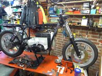
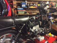
A bit stop start this project but even though it might not look it I've made a lot of progress over the last few days. To be fair I have done a lot of work this summer on other bikes....
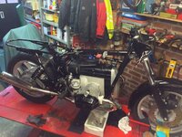
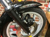
Anyway the main work has been sorting the wiring out which is just about done. I will need to tidy up the runs but I'll do this once I've got the cables installed and get it off the bench. I need to be able to move the forks around and also satisfy myself that I'm happy with the bars before I settle on cable lengths.
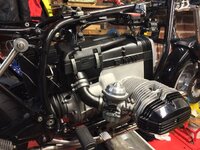
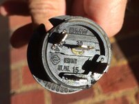
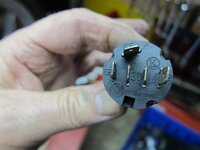
I am having a bit of an issue with the ignition switch. The original one pictured is the 5 pin one which was mounted in the fairing and is installed temporarily. The centre two pins appear to be both numbered 30. The switch I want fits in the centre of the plastic console as shown. I tried the usual suppliers for the correct fitting one but the best I could do was get the 4 pin one shown from
Sherlock FOC as it was part of a big order and no guarantees it would work. Well I've tried most obvious combinations of connection and I can't get the
Sherlock one to work. Two possibilities: 1. It's broken 2. Which is quite likely, I've not got the right connections made. I assumed 15->15 and 30->30 to start which seem correct from the wiring diagrams. The hidden pin number on the 4 pin switch is 58E. According to the Haynes manual this is the correct switch for my bike but my wiring colours don't match (but I am colour blind.......

).
Incidentally the wiring diagrams are one area where it seems the Haynes wins over the Clymer manual.
I can make up a fitting for the original switch but would rather get the right one. Anybody got an idea of the correct way to make the connections or have a suitable one for sale?
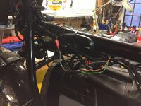
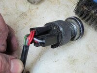
One more thing, the yellow wire in the heated grip harness shown gets almost too hot to touch when it's on Low setting. I assume this is a resistance wire. Is it normal for it to get so hot?
Cheers
David


 The problem I've had is that the colouring of the wires doesn't tie in with any of the wiring diagrams in the manuals
  Too many reds......at least I think there are....