

You are using an out of date browser. It may not display this or other websites correctly.
You should upgrade or use an alternative browser.
You should upgrade or use an alternative browser.
Dogbytes' R80 ST project
- Thread starter Dogbytes
- Start date
markjackson
Registered user
Here's one

Glad to see you soon got out of that featal position in the corner of the garage 
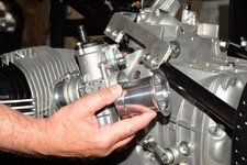
It'll just look "trick" if you cut the velocity stack to miss the bracing tube. It always makes me smile when you look at track bikes, they're generally as rough as hell. Richie was saying they don't even bother to paint the frames on their race bikes and run them as bare steel.
It'll just look "trick" if you cut the velocity stack to miss the bracing tube. It always makes me smile when you look at track bikes, they're generally as rough as hell. Richie was saying they don't even bother to paint the frames on their race bikes and run them as bare steel.
Please Sir! What's a velocity stack? (either at home or otherwise)
Please Sir! What's a velocity stack? (either at home or otherwise)
It's where you stack your velocities!

it's the intake part on the carb, different lengths effect torque and power at different engine speeds much in the same way as exhausts do, mostly they are hidden in the airbox, but you can see them if you use a stack, with a filter on the end, some modern bikes actually have motors that alter the length of the stacks depending on RPM.
Deleted account 200123001
Registered user
- Joined
- Mar 4, 2014
- Messages
- 2,372
- Reaction score
- 0
The inlet to the carb. The length and diameter of the intake are selected to suit the application.Please Sir! What's a velocity stack? (either at home or otherwise)
Long tubes generate low end torque, but starve top end power and visa versa.
The change in diameter also serves to speed up the velocity of the air to create an overcharging effect where the high velocity of the incoming air compresses the air already in the cylinder with its own mass to try and get more air into the cylinder. At higher rpms the resistance can become too great impeding the engine.
I believe the 1150 RT has different intake tubes from the air box to the Throttle body than the GS does.
It's where you stack your velocities!
it's the intake part on the carb, different lengths effect torque and power at different engine speeds much in the same way as exhausts do, mostly they are hidden in the airbox, but you can see them if you use a stack, with a filter on the end, some modern bikes actually have motors that alter the length of the stacks depending on RPM.
Every day is a school day. Thanks for the explanation.

The inlet to the carb. The length and diameter of the intake are selected to suit the application.
Long tubes generate low end torque, but starve top end power and visa versa.
The change in diameter also serves to speed up the velocity of the air to create an overcharging effect where the high velocity of the incoming air compresses the air already in the cylinder with its own mass to try and get more air into the cylinder. At higher rpms the resistance can become too great impeding the engine.
I believe the 1150 RT has different intake tubes from the air box to the Throttle body than the GS does.
Who knew there was so much to it? Obviously not me.
Deleted account 200123001
Registered user
- Joined
- Mar 4, 2014
- Messages
- 2,372
- Reaction score
- 0
Oh yeah......its for those who are more interested in trying to ride faster than just riding....
Oh yeah......its for those who are more interested in trying to ride faster than just riding....
I'll have you know my velocities are well stacked fnar fnar
Glad to see you soon got out of that featal position in the corner of the garage
It'll just look "trick" if you cut the velocity stack to miss the bracing tube. It always makes me smile when you look at track bikes, they're generally as rough as hell. Richie was saying they don't even bother to paint the frames on their race bikes and run them as bare steel.
It's all true. I remember reading about Laverda SFCs being delivered with no paint on the frames because they just expected people to weld fairing mounts, etc onto them. The flip side (ain't there always one!) is that the one complete bike of Richie's that I've seen was a 'Paris Dakar replica' that was so flawlessly finished that it defies words.
There's more to it but I'm going to delay any drastic action. Richie would rather I just cut the frame braces out but for various reasons that won't be happening (yet!). The main reason for that is that those carbs and trumpets just won't fit as things are and any changes to Richie's set up is going to be detrimental to how the engine runs. Very detrimental indeed, apparently. However I need to finish this bike and then worry about fettling. In the short term I'm going to fit the smallest, 35 or 36mm trumpets - which probably still need some mods. But I have a two possible long term solutions. Watch this space...
charlie b
Registered user
I believe the 1150 RT has different intake tubes from the air box to the Throttle body than the GS does.
I had 1100GS intake tubes fitted onto my 1100RT, it did make an appreciable improvement in mid range torque, a useful mod.
Mr Moore will surely have some thoughts on this John..?

(Motor does look splendid, BTW..!!)
I had 1100GS intake tubes fitted onto my 1100RT, it did make an appreciable improvement in mid range torque, a useful mod.
Mr Moore will surely have some thoughts on this John..?
(Motor does look splendid, BTW..!!)
Ah, Mr B, hello! Yes, it is starting to look quite pretty and yes, Richie does have some, very well informed, thoughts but then he has the luxury of only being concerned with the motor and I have to take a more holistic view. I will sort it out in such a way that he'll be happy though.
markjackson
Registered user
Please Sir! What's a velocity stack? (either at home or otherwise)
Although I studied fluid dynamics as a core part of a Mech Eng Degree, I learned far more from reading the work of the late John Robinson which covered the subject as part of chassis tuning (drag), exhaust tuning (pressure waves) and intake tuning (more pressure waves, optimum velocities and venturi effect).
What useful and simple principles I do remember (and it's not much) is that high speed air has lots more friction than you would think, hates changing direction and behaves in a fairly consistent way when its flow is interrupted and restarted (like before or after a valve in an engine).
The way I imagine it…
In the intake system the air behaves like a big group of people wanting to leave a big building standing in a lobby then suddenly, all running towards one opening lift. When the door opens some of the people go in, but many are left outside. The surge forward of the mass of people is stopped when the doors close, and the assembled crowd at the lift door start to relax and wander back into the lobby. The people behind them take a little longer to stop moving forwards, and a bit of a squash happens in the middle of the lobby. Then the doors open again and the people at the front are pushed forward to get in to the lift. I imagine this cycle on a loop to replicate the intake system.
But… While the architect doesn't want anyone crushed in the lobby, an engine designer would love to see this. They actively seek to create the highest pressure ready to rush the valve as soon as it opens, so they design the intake length, (from intake valve to bell mouth outer tip or sometimes air box lid) to make the crowd stay pushing at the lift doors. In the human example this would be a corridor from the lobby to the lift doors.
When a 4 stroke engine runs at a medium crank speed (say a single at 6,000 rpm), the air flow coming in to each cylinder is stopped suddenly by the closing intake valve 3000 times every minute. Each time the valve shuts a 'backing-up' pressure wave creates a higher pressure area behind it, which would quickly equalise to atmospheric pressure if the valve didn't open again, milliseconds later. The perfect situation for the engine designer is that the higher pressure wave (the crush in the lobby) fills the whole intake tract, but does not spill out of the end (the bell-mouth) and drop the pressure.
The time available for the higher pressure to dissipate is proportional to engine speed as there will be a valve opening again very soon if you are near the redline, or a long wait at tick-over. The time taken for the pressure wave to reach back to the atmosphere (the world outside the bell-mouth) at that particular air speed is determined by the length of the 'corridor' from the closing valve, back through the carb to the end of the bell-mouth.
If, at our 6000rpm engine speed, the compression effect works perfectly, and the pressure wave maximised the pressure throughout the intake tract, the cylinder filling will be optimised and the intake length will be contributing its best efforts to increasing torque at that RPM.
Down at 2000 rpm, with more time before the valve opens again, the pressure wave would have escaped, so we would need a longer intake tract to trap it and get the intake length benefit down there. A really long corridor will always trap it, but the drag of the air against the intake wall (the friction thing) will reduce the efficiency of the engine at all speeds, so not perfect for a racer.
Up at 10,000 rpm, our pressure wave (the crush in the lobby) would only be getting half way back from the valve to the atmosphere, so we would need a shorter manifold, carb and bell mouth to get maximum intake efficiency at such high revs. The shortest intake also creates the lowest drag, which helps peak power.
It's my simplified understanding, and almost certainly 'too-simple' for peeps that really understand all the science, but I've seen it work very clearly in practice on both intake and (expansion chamber) exhaust systems when racing little 2 strokes as a skinny youth
P.S It's much easier to see the tuned length (from exhaust port back to the converging cone) on two stroke exhausts: Compare a 175 MZ (designed to be good at low revs) to a 350 TZ (still the same capacity per pot, but designed to have a narrow power band at high revs). One is long 'n thin, while the latter is very short & fat.
markjackson
Registered user
Ooh… Sorry for the massive thread hijack!
We clearly need more R80ST project pictures to keep the thread from drifting!
We clearly need more R80ST project pictures to keep the thread from drifting!
Although I studied fluid dynamics as a core part of a Mech Eng Degree, I learned far more from reading the work of the late John Robinson which covered the subject as part of chassis tuning (drag), exhaust tuning (pressure waves) and intake tuning (more pressure waves, optimum velocities and venturi effect).
What useful and simple principles I do remember (and it's not much) is that high speed air has lots more friction than you would think, hates changing direction and behaves in a fairly consistent way when its flow is interrupted and restarted (like before or after a valve in an engine).
The way I imagine it…
An excellent analogy. However I've now learned my lesson and so the next one will have supercharger to render all the above irrelevant. I'll leave you to explain why!
")
PS David Vizard also wrote some good articles on it, back in the day...
Ooh… Sorry for the massive thread hijack!
We clearly need more R80ST project pictures to keep the thread from drifting!
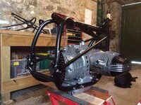
No sooner said than done!
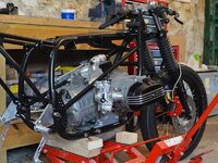
Here's a pic of the issue under discussion. Having decided it needed further consideration, I moved on to installing the front end - new steering head bearings, naturally. It's the first time a wheel and tyre have been on it for ages! I still have to make the adaptor to hold the rear wheel in the wheel building jig to true and tension it.
I then stripped to old bearing races out of the swing arm (complete pain). Will build it back up tomorrow. I've painted the bevel box too, so that can be built back up as well.
Attachments
markjackson
Registered user
PS David Vizard also wrote some good articles on it, back in the day...
A friend emailed tonight to say he was starting the restoration of his old Mini…
Vizard's 'Tuning the A series engine' book was the first thing I though of!
Back on topic… Great pics
A friend emailed tonight to say he was starting the restoration of his old Mini…
Vizard's 'Tuning the A series engine' book was the first thing I though of!
Back on topic… Great pics
I remember reading an article illustrated with pics of him setting the valve clearances on a Ford cross flow (Kent engine?) with a dial gauge.
Obviously I'll be doing the same on this engine...

Similar threads