had the thing to bits, no voltage to the wire terminals at the light, traced it back can see no damage
anything common here going on or am i just lucky?
anything common here going on or am i just lucky?


It's easy.
First substitute the earth for a known good earth at the bulb end if it works it's a bad earth.
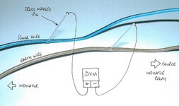
If it still doesn't work, get yourself a dress makers pin and push it through the insulation of the power wire, moving away from the light until you get power.
That will show you if it's not to obvious visually where the break is.
so i earth the indicator end - right ive learned a new trick there thanks.
NOW what do i connect to the pin? the earth cable?
...........................nothing on the ohmeter from the black cable to the same earth, so looks like an earth problem.
bugger.
I think he means get a pin and test meter (or a bulb with wires attached to it). Connect the black test lead (or bulb earth) to earth and then attach the pin to the red test lead (or the wire connected to the bulb contact terminal). Stab the live indicator lead with the pin at points between the indicator and the power source until the meter shows voltage (or the bulb glows). You'll either find a break in the wire or have crossed a connector which will prove to be not connecting. A clever trick that I've never heard before.