R100GSPD Not charging

Wierpig

Well-known member
UKGSer Subscriber
Joined
Aug 20, 2006
Messages
1,411
Reaction score
296
Location
merseyside
Its a 95 bike and Ive just put the timing cover back on after some engine work. Now its not charging. Ive been over the location and condition of all the relevant connectors. All good. The charging light comes on with ign and stays on. If I short the black and blue wires at the regulator, the light dims over 2000rpm but the voltage at the battery doent rise.
The rotor resistance between the slip rings is 7.0 ohms. Not sure how critical this is, but its outside spec by a couple of ohms.
AC voltage at all the alternator phase wires is 4v each.
Any thoughts? I did have to airgun the rotor bolt off as the hulk had tightened it.
 
When you took the front cover off, you did take the negative lead off the battery before removing/refitting it?
I may be teaching granny how to suck eggs, but if the battery is still connected, it’s possible to short out the diode board when moving the front cover.

Do you have another diode board you can fit to see if this is the problem?
If not. Check all wiring connectors in case you have inadvertently dislodged something….again, I’m not trying to teach you to suck eggs.

….and how old is the battery ? …...maybe it’s on its way out.
 
I don't know what the 90s bikes had for alternators .... but my /5 did the same thing, and it turned to be that the rotor winding in the alternator opened .... And the shop at that time had rotors that had been rewound and covered in epoxy. And I put that in. It was very difficult to solder the brushes on though and I still worry that it will come apart as I never got the solder hot enough to flow really but it has 50000+ on it since then.
I believe you can get a rare earth magnet alternator for them now which will eliminate the brushes ..... That circuit that runs thru the rotor on the /5 goes thru a bunch of other stuff strangely, and none of that will work when the rotor is open. you should be able to check the rotor winding to see if it is open ..... it has very fine wire and is easily damaged ...
Other wise you may have forgot to hook something up .... good luck
 
I did disconnect the battery before starting and it is in excellent condition. I do suspect the rotor but the resistance test is showing nearly correct figures. I think I read that if the rotor failed, the charging light doesnt work at all..ie doesnt illuminate at ign on.
 
I don't know what the 90s bikes had for alternators .... but my /5 did the same thing, and it turned to be that the rotor winding in the alternator opened .... And the shop at that time had rotors that had been rewound and covered in epoxy. And I put that in. It was very difficult to solder the brushes on though and I still worry that it will come apart as I never got the solder hot enough to flow really but it has 50000+ on it since then.
I believe you can get a rare earth magnet alternator for them now which will eliminate the brushes ..... That circuit that runs thru the rotor on the /5 goes thru a bunch of other stuff strangely, and none of that will work when the rotor is open. you should be able to check the rotor winding to see if it is open ..... it has very fine wire and is easily damaged ...
Other wise you may have forgot to hook something up .... good luck
It's essentially the same set up. Looking at the original post above, it seems there's continuity in the windings but with a higher resistance than expected?
 
I did disconnect the battery before starting and it is in excellent condition. I do suspect the rotor but the resistance test is showing nearly correct figures. I think I read that if the rotor failed, the charging light doesnt work at all..ie doesnt illuminate at ign on.
How about the earths? Worth checking ...
 
I did disconnect the battery before starting and it is in excellent condition. I do suspect the rotor but the resistance test is showing nearly correct figures. I think I read that if the rotor failed, the charging light doesnt work at all..ie doesnt illuminate at ign on.
///////////
It was a long time ago, but it seems to me that the charging light stays on. In fact that is what got me to pull over and start checking things. This was the only time the /5 came close to leaving me stranded. After I determined that I wasn't going to be able to fix it on the road, I rode down a ways toward home and then stopped at a full service station and had the guy charge the battery and I made it home on that charge ....
i would try to check the winding continuity on the winding side of the rotor winding, just to make absolutely sure the winding isn't open at all, and the brushes/rings aren't interfering somehow. And you also may be able to start it up and follow the voltage, seeing if there is three phase voltage before the the diod bank and the after the diod bank and so on ....
 
///////////
It was a long time ago, but it seems to me that the charging light stays on. In fact that is what got me to pull over and start checking things. This was the only time the /5 came close to leaving me stranded. After I determined that I wasn't going to be able to fix it on the road, I rode down a ways toward home and then stopped at a full service station and had the guy charge the battery and I made it home on that charge ....
i would try to check the winding continuity on the winding side of the rotor winding, just to make absolutely sure the winding isn't open at all, and the brushes/rings aren't interfering somehow. And you also may be able to start it up and follow the voltage, seeing if there is three phase voltage before the the diod bank and the after the diod bank and so on ....
Ive remove and cleaned he rotor. Its got 7ohms between the rings. Well, thinking about it...its almost double what it should be.
 
Ive remove and cleaned he rotor. Its got 7ohms between the rings. Well, thinking about it...its almost double what it should be.
7 ohms is a very small amount for that. It sounds like way too little (a short) to me as the winding is intended to have high impedance, very small diameter wire and very long too. If the winding is in fact intact there is no way it can't make power out of the alternator, it has to have power there. Then the three phase AC power out of the alternator is converted to DC. How it charges the battery I don't know or if the current is always there and only charges when the battery is drained a little by loads.
just follow the power ..... it could be the diode board too .... you'll figure it out .....
 
7 ohms is a very small amount for that. It sounds like way too little (a short) to me as the winding is intended to have high impedance, very small diameter wire and very long too. If the winding is in fact intact there is no way it can't make power out of the alternator, it has to have power there. Then the three phase AC power out of the alternator is converted to DC. How it charges the battery I don't know or if the current is always there and only charges when the battery is drained a little by loads.
just follow the power ..... it could be the diode board too .... you'll figure it out .....
OK I just looked it up on AI .... I was wrong, there is a fairly low resistance there. for 1991 and newer its supposed to be 2.8 ohms. for older bikes from the 70's it's supposed to be 3.4. The fact that there using tenths there suggests that this is in fact very exact and could be the problem considering your several times more resistance. Why it woulds suddenly have more resistance I don't know.
This could be a great opportunity to try an earth magnet alternator in it .....
 
OK I just looked it up on AI .... I was wrong, there is a fairly low resistance there. for 1991 and newer its supposed to be 2.8 ohms. for older bikes from the 70's it's supposed to be 3.4. The fact that there using tenths there suggests that this is in fact very exact and could be the problem considering your several times more resistance. Why it woulds suddenly have more resistance I don't know.
This could be a great opportunity to try an earth magnet alternator in it .....
more trivia .... as I read further, it seems that /5 bikes have 6.9 ohms. They also said that intermittent opens are also common. But the difference in the rotor resistance just controls how soon the alternator starts charging. the newer 91+ bikes will charge at much lower rpms that the /5 at 6.9 ohms. so in theory that shouldn't be a deal breaker. Maybe someone put a rotor in it that is for a /5?
Oh well, I myself wanted to upgrade to the earth magnet because of the soldering job I did on the brushes. But I bought a new RS and it still sits ...
And they did say that the alternator light does stay on .....
To find this info I googled ...... ohms of resistance for bmw airhead alternator rotor ......
 
Its a 95 bike and Ive just put the timing cover back on after some engine work. Now its not charging. Ive been over the location and condition of all the relevant connectors. All good. The charging light comes on with ign and stays on. If I short the black and blue wires at the regulator, the light dims over 2000rpm but the voltage at the battery doent rise.
The rotor resistance between the slip rings is 7.0 ohms. Not sure how critical this is, but its outside spec by a couple of ohms.
AC voltage at all the alternator phase wires is 4v each.
Any thoughts? I did have to airgun the rotor bolt off as the hulk had tightened it.
7 Ohms puzzling - an old rotor or a faulty Ohmmeter. Anyway, it is closed circuit, a good thing. Not sure if an old rotor is a good fit to a later stator....earlier is 73.4mm diameter, later is 73mm? Could be your issue. Old stator 105mm, your bike should have 107mm diameter stator.

Shorting blue and black - your test results show VR ok and either rotor, stator, diode board or wiring at fault (ref Rick Jones 'Classic Boxer Charging' book). You have checked the wiring and the rotor is as above. That leaves Stator and Diode board. 4VAC is too low for the stator output - look for 13VAC at tickover and up to 24VAC at higher revs. Check your meter, or the rotor could be giving spurious output. Diode Board - earthed properly?

What 'engine work' did you do, did you change components or is it a new-to-you bike? Some context needed here.
 
7 Ohms puzzling - an old rotor or a faulty Ohmmeter. Anyway, it is closed circuit, a good thing. Not sure if an old rotor is a good fit to a later stator....earlier is 73.4mm diameter, later is 73mm? Could be your issue. Old stator 105mm, your bike should have 107mm diameter stator.

Shorting blue and black - your test results show VR ok and either rotor, stator, diode board or wiring at fault (ref Rick Jones 'Classic Boxer Charging' book). You have checked the wiring and the rotor is as above. That leaves Stator and Diode board. 4VAC is too low for the stator output - look for 13VAC at tickover and up to 24VAC at higher revs. Check your meter, or the rotor could be giving spurious output. Diode Board - earthed properly?

What 'engine work' did you do, did you change components or is it a new-to-you bike? Some context needed here.
Check my tappet spalling thread below for history (y) The bike has only done 35000 miles and everything looks original. It was charging fine until I stripped it. Im wondering if the vibration of the airgun has damaged the rotor.
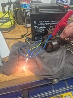
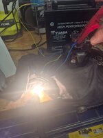
 
Tried passing a current through the rotor. Ive been caught out like this before. Static resistance test is ok but when you ask the circuit to do any work it fails...
First picture is through the rotor20260801_122048.jpgsecond is direct to the bulb.Surely thats more than 7ohms of resistance?
20260801_122052.jpgand the rotor got too hot to touch.
 

Attachments

  • 20260801_122048.jpg
    20260801_122048.jpg
    173.3 KB · Views: 0


Back
Top Bottom