fred_jb
Registered user
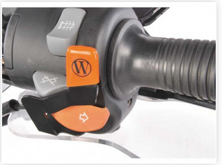
In a post on my recent tour to Spain and Portugal I mentioned that one of my few niggles with the bike was the awkward reach to the indicator switch due to the presence of the wonderwheel, and the consequent high probability of jogging the wheel instead of, or as well as, activating the indicators. This seems to have struck a chord, with quite a few other people commenting that they have the same problem. In my opinion this is poor design by BMW in that they have sacrificed ease of use of a primary safety related control, i.e. the indicator switch, in order to provide easy access to a secondary, non-essential, and optional control, i.e. the GPS multicontroller.
This means that unless you have large hands, reaching the indicator, especially to activate the left turn signal, is a real stretch needing you to partially release your grip on the bar. Having done that it is then almost impossible to be sure of your thumb position or rely entirely on feel in using the indicators, because the jog wheel is very close and feels very similar, which means you end up continually checking the instrument panel to be sure that your indicators are actually on. In addition, if you are using the GPS, then accidentally jogging the wheel causes further distraction as you try to work out which way you jogged it, and end up faffing about with it trying to get the map back.
I found this was extremely annoying, especially on long motorway stints where I feel it is very important to signal a lane change, going out and returning to your original lane, and I believe a legal requirement to do both in some countries. Because in my case it is primarily a problem with having to stretch to reach the indicator switch, and not just a position thing which I could get used to, then there is no easy solution, except to dispense with the wonderwheel. This is exactly what I have just done, and below are a couple of pictures of the end result.
I do intend to investigate alternative ways of providing the same functionality as the wheel, either by mounting a modified wheel elsewhere, or preferably by taking over its functions using some form of mini joystick or navigation pad. I will post again with details if I succeed in doing this


In case it is useful to anyone else, here is a description of the process of removing the wheel, with the usual proviso's that you do this entirely at your own risk and you should only regard anything I have written as a guide and not necessarily definitive, or even entirely correct.
Unfortunately the heated grip required for use without the multicontroller is different to the one used with it, so the first requirement is to buy the appropriate part, which for my 2017 GS is part number 61318552115. I bought this online from Rainbow Motorcycles for £70.70, and because I was buying a few other things I got free postage, but otherwise it would be a rather steep £10.
The heated grip and wheel assembly pushes into the LH switch cluster and locks into it with a springy plastic tab which drops into a hole inside the switch cluster moulding adjacent to the bar. This is not accessible from the outside, and in any case is locked into position by the bar itself, so it is necessary to remove the complete grip, wheel and switch cluster off the bar in order to get at this tab from the inside and release it, allowing the grip/wheel assembly to be split from the switch cluster.
The first thing to do is remove the bolt which goes right through the heated grip and holds the complete assembly in place and prevents it rotating. You can get at this by folding back the rubber flange next to the wheel on the side facing the rider. Once this is out the complete assembly can be moved along the bar a bit and rotated to make further disassembly easier, but be careful not to strain the cables. I actually released them from their clips and turned the bars fully to the left to get more slack.
You then need to release the heated grip connector and the switch cluster connector. To do this you need first remove the small cover over the cable entry to the switch cluster. This just clicks onto the main lower plastic cover and is held on by two plastic tabs which you can just ease out with a fingernail, taking care not to break them off. You can then remove the 6 way switch cluster connector which is the one with the thicker cable and positioned furthest from the bar. This seems to just pull out, I couldn't see any locking tab on it.
Once this is out you can then remove the heated grip connector. I found I was unable to do this without first removing the main part of the lower cover, but it may be possible to do so without. This cover is held on by two screws and clicks together to the top half with some plastic tabs which can be persuaded to release more easily by gently pushing them inwards with a small screwdriver, taking care not to be too forceful and break them. Alternatively just squeezing the top cover inwards a bit seems to work. Once this is off you can more easily access the heated grips 2 way connector. This one is definitely locked into place with a plastic tab. This is at the back, i.e. right next to the bar itself and although you can't see it you can slide a small screwdriver down the back of the connector and push away from the connector and towards the bar. This should flex the locking tab and allow you to pull the connector out. If it doesn't come out easily then you have not released the tab, so try re-positioning the screwdriver and try again.
Once you have the two cables disconnected, the complete grip, wheel and switch cluster assembly can be slid off the bar, after unbolting the hand guard and bar end weight. To separate the switch cluster from the grip/wheel assembly the plastic tab mentioned earlier needs to be lifted up and the grip/wheel assembly will then just slide out, disengaging the wheel's 6 way connector in the process. In the following picture the 2 way heated grip connector is at the top and you can see its locking tab to the right. The other connector is the 6 way connector which links the wheel to the switch cluster via a matching socket inside the switch cluster which it engages with. Below that is the plastic prong containing the tab, just to the right of the white label, which locks the grip/wheel assembly into the switch cluster.
The new wheelless grip can then be inserted into the switch cluster, and reassembly is just the reverse process.
Fred

This means that unless you have large hands, reaching the indicator, especially to activate the left turn signal, is a real stretch needing you to partially release your grip on the bar. Having done that it is then almost impossible to be sure of your thumb position or rely entirely on feel in using the indicators, because the jog wheel is very close and feels very similar, which means you end up continually checking the instrument panel to be sure that your indicators are actually on. In addition, if you are using the GPS, then accidentally jogging the wheel causes further distraction as you try to work out which way you jogged it, and end up faffing about with it trying to get the map back.
I found this was extremely annoying, especially on long motorway stints where I feel it is very important to signal a lane change, going out and returning to your original lane, and I believe a legal requirement to do both in some countries. Because in my case it is primarily a problem with having to stretch to reach the indicator switch, and not just a position thing which I could get used to, then there is no easy solution, except to dispense with the wonderwheel. This is exactly what I have just done, and below are a couple of pictures of the end result.
I do intend to investigate alternative ways of providing the same functionality as the wheel, either by mounting a modified wheel elsewhere, or preferably by taking over its functions using some form of mini joystick or navigation pad. I will post again with details if I succeed in doing this
In case it is useful to anyone else, here is a description of the process of removing the wheel, with the usual proviso's that you do this entirely at your own risk and you should only regard anything I have written as a guide and not necessarily definitive, or even entirely correct.
Unfortunately the heated grip required for use without the multicontroller is different to the one used with it, so the first requirement is to buy the appropriate part, which for my 2017 GS is part number 61318552115. I bought this online from Rainbow Motorcycles for £70.70, and because I was buying a few other things I got free postage, but otherwise it would be a rather steep £10.
The heated grip and wheel assembly pushes into the LH switch cluster and locks into it with a springy plastic tab which drops into a hole inside the switch cluster moulding adjacent to the bar. This is not accessible from the outside, and in any case is locked into position by the bar itself, so it is necessary to remove the complete grip, wheel and switch cluster off the bar in order to get at this tab from the inside and release it, allowing the grip/wheel assembly to be split from the switch cluster.
The first thing to do is remove the bolt which goes right through the heated grip and holds the complete assembly in place and prevents it rotating. You can get at this by folding back the rubber flange next to the wheel on the side facing the rider. Once this is out the complete assembly can be moved along the bar a bit and rotated to make further disassembly easier, but be careful not to strain the cables. I actually released them from their clips and turned the bars fully to the left to get more slack.
You then need to release the heated grip connector and the switch cluster connector. To do this you need first remove the small cover over the cable entry to the switch cluster. This just clicks onto the main lower plastic cover and is held on by two plastic tabs which you can just ease out with a fingernail, taking care not to break them off. You can then remove the 6 way switch cluster connector which is the one with the thicker cable and positioned furthest from the bar. This seems to just pull out, I couldn't see any locking tab on it.
Once this is out you can then remove the heated grip connector. I found I was unable to do this without first removing the main part of the lower cover, but it may be possible to do so without. This cover is held on by two screws and clicks together to the top half with some plastic tabs which can be persuaded to release more easily by gently pushing them inwards with a small screwdriver, taking care not to be too forceful and break them. Alternatively just squeezing the top cover inwards a bit seems to work. Once this is off you can more easily access the heated grips 2 way connector. This one is definitely locked into place with a plastic tab. This is at the back, i.e. right next to the bar itself and although you can't see it you can slide a small screwdriver down the back of the connector and push away from the connector and towards the bar. This should flex the locking tab and allow you to pull the connector out. If it doesn't come out easily then you have not released the tab, so try re-positioning the screwdriver and try again.
Once you have the two cables disconnected, the complete grip, wheel and switch cluster assembly can be slid off the bar, after unbolting the hand guard and bar end weight. To separate the switch cluster from the grip/wheel assembly the plastic tab mentioned earlier needs to be lifted up and the grip/wheel assembly will then just slide out, disengaging the wheel's 6 way connector in the process. In the following picture the 2 way heated grip connector is at the top and you can see its locking tab to the right. The other connector is the 6 way connector which links the wheel to the switch cluster via a matching socket inside the switch cluster which it engages with. Below that is the plastic prong containing the tab, just to the right of the white label, which locks the grip/wheel assembly into the switch cluster.
The new wheelless grip can then be inserted into the switch cluster, and reassembly is just the reverse process.
Fred