automotive relays

roddy

Registered user
Joined
Apr 1, 2005
Messages
2,742
Reaction score
0
Location
To the East of the Dear Green Place
HI folks

Is the numbering system on automotive relays, standard or does it change depending on company ?

I 'm making up a wiring loom for some lights for my 1150GSA and just what to make sure.

cheers
 
Roddy,
You may find the following useful.
I have a superb Word document if you would like to contact me so that I can email it to you.

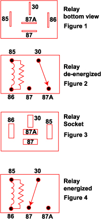
What do #'s like 86a mean?
Terminal # = function
15 = Switched positive output from battery
30 = Postive output direct from battery (+)**
31 = Direct to battery negative ( - ), ground
31b = Return to battery negative via switch or relay
49 = Positive input for turn signal flasher
49a = Turn signal flasher trigger power to switch (54); marking used after /5
54 = Turn signal switch contact from flasher (49a); marking used on /5
85 = Relay trigger wire, generally for negative/ground winding on electromagnet**
86 = Relay trigger wire, generally for positive winding on electromagnet**
86a = Path to ground via neutral switch with diode (prevents "NEU" from lighting via clutch switch [contact 86] )**
87 = Normally open relay output, generally**
87a = Normally closed relay output
87b = Second normally open relay output on a seperate throw
D+ = Voltage Regulator/Dynamo (Alternator) positive
C or KBL = power to turn signal indicator light in gauge cluster
 
I have prob that you may be able to help me with. Have relay with diode. I am told that it is essential that the switching live and neutral/earth (in my case the two wires from the horn push) be connected correctly. Any info please. (What happens if you connect them the wrong way round-does it damage the relay?

Jeff
 
A diode is an electricity one way valve, so if you connect it the wrong way round the electrickery can't flow. If you find that it's not working, switch the terminals round.
 
HI folks

Is the numbering system on automotive relays, standard or does it change depending on company ?

I 'm making up a wiring loom for some lights for my 1150GSA and just what to make sure.

cheers


The simple answer is yes, they should be standard.

Nearly all modern relays are 'ISO relays' ISO being the International Standards Organisation.....there are various types, sizes and fancy bits (like the diode mentioned above) but they should all pretty much be marked up in the same way, and a pin86 on one will serve the same as a pin86 on any other ISO Relay.

ISO-relay.jpg


That's your standard 5 pin ISO relay
 
The simple answer is yes, they should be standard..........

Shabby service there Fanum, nearly 4 years after I asked the question :D

I have prob that you may be able to help me with. Have relay with diode. I am told that it is essential that the switching live and neutral/earth (in my case the two wires from the horn push) be connected correctly. Any info please. (What happens if you connect them the wrong way round-does it damage the relay?

Jeff

You always want to switch the live wire, that way when the relay is disconnected the power is stopped to the item, if you do it the other way and a fault developes a path for return to earth may emerge meaning the item is always on.

Without a bit more info it's hard to advise on correct wiring
 
Relays

They all have a diagram of contacts on the cover so no probs there.
 
diode on relay

Jeff, I think you have hijacked roddys thread, but in answer to your question the diode is placed across the coil. Its purpose is to absorb the back emf from the coil when it is switched off. We used to call them clamping diodes and they were generally found in circuits switched by transistors, which needed protection from this 'spike'. If you connect the coil (of the relay) the wrong way round you are going to short the coil out, make sure you get it the right way round.


Back
Top Bottom