Comfy old boots bike service resto thread

This looks fairly straight forward:


Edit. Just read this


So this might take me a little time to work out. Peaning the aluminum down does not seem the best idea long term

and just putting this in here so i can find it later


Last edited:
Right, so here is what is going to happen. Because I've bought a replacement motor, the air will mysteriously disapear and the brakes will be perfect. This will happen just before i do the folllowing:

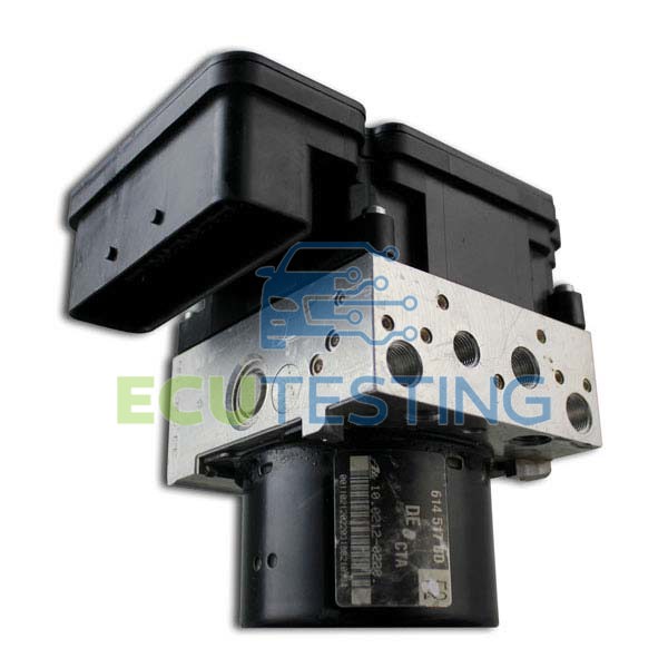
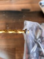
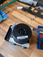
I've bought a tap and die set. I've bought a good quality 3.3mm hss drill bit that looks like it's suitable for aluminium. I'll drill and tap the ford unit to M4. If this goes well I'll do it again on my BMW unit.

I really like the way NIN has done his in the post above. Neat. Tidy. None of this whacking the crap out of stuff. I like the way it's drilled into what is obviously a thicker bit of aluminum casing. I'm not sure how cleanly I can remove the tab but i've a dremmel and loads of attachments so i'll figure out something. I'll buy some suitable steel bar locally and cut to size.

What could go wrong? :hide
 
Last edited:
Be very careful drilling into the aluminium block, there are oil galleries in there and you'll ruin the unit. Rather than faffing, send it to these guys and get it back properly sorted and guaranteed for life (y)

 
Be very careful drilling into the aluminium block, there are oil galleries in there and you'll ruin the unit. Rather than faffing, send it to these guys and get it back properly sorted and guaranteed for life (y)

I’m fool hardy in the extreme perhaps

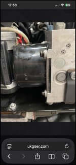
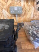
IMG_7324.jpg

But there is the depth of the four lugs plus maybe a mm before trouble. I’m going to try it with my hand drill on the ford unit. If I’m not happy with that I’ll bring the bmw unit to work and use a pillar drill. I’ll not come crying if I mess it up.

I will quite possibly drink too much and rant a bit 🤪
 
So I've been using google AI to help me figure out what is going to happen when I have my new coils and mercury gauges in hand. This seem accurate? Sorry if it's a bit verbose but this is what it's given me. I've been trying to corroborate it posts on here and it seems reasonably accurate.

__________________________________________

This information is for general knowledge only and should not be taken as medical advice. You should consult with a healthcare provider if you have any health-related concerns. :aidan

-----------------


Here is the exact, step-by-step procedure for a 2007 BMW R1200GS (Hexhead) starting immediately after you have finished adjusting the valves.

Phase 1: Throttle Cable Slack Check (Engine Off)
Before starting the bike or checking the balance, you must ensure the throttle cables are not pulling the throttle bodies open at idle.
  • Locate the cable adjusters: They are on top of each throttle body.
  • Set initial slack: Ensure there is roughly 1mm to 2mm of free play in both the left and right throttle cables.
  • Verify butterfly stops: Twist the throttle and let it snap shut. You should hear a distinct metallic "click" on both sides as the throttle pulleys hit their mechanical stop screws. (Note: Never adjust these painted mechanical stop screws).

Phase 2: Electronic Idle Lock (Using GS-911)
The 2007 R1200GS utilizes dual electronic idle actuators (stepper motors) to control idle air. To get an accurate sync, you must lock these actuators so they do not try to fight your manual adjustments.
  1. Connect your yellow GS-911 to the bike and your Windows PC. Turn the ignition ON.
  2. Start the engine and let it run until it reaches operating temperature (at least 4 bars on the instrument cluster display). Do not let the bike idle stationary for more than 10 minutes to avoid overheating the air-cooled cylinders. Place a fan in front of the engine if needed.
  3. In the GS-911 software, navigate to: Engine Controller (BMS-K) -> Service Functions.
  4. Select Lock Idle Actuators (or Lock Stepper Motors). This centers and locks both actuators into a fixed position.

Phase 3: Mechanical Synchronization (Engine Running)
  1. Hook up your vacuum gauge: Attach your twin-channel manometer (e.g., Harmonizer, TwinMax, or vacuum sticks) to the vacuum ports underneath each throttle body. Remove the small rubber blanking caps to expose the nipples.
  2. Check Idle Balance: With the engine running and the GS-911 locking the steppers, check your gauge.
    • If the idle is out of balance: Do not adjust the cables. An un-syncing at idle usually means air leaks at the rubber intake boots, dirty throttle bores, or dirty stepper motors.
  3. Sync off-idle (3,000 to 3,500 RPM): Hold the throttle steady at roughly 3,500 RPM. Look at your vacuum gauge.
    • If the gauge is uneven: Loosen the locking nut on the RIGHT-HAND side throttle cable adjuster. Turn the adjuster until your vacuum gauge reads perfectly even (0 differential pressure).
    • Why the right side? The left side cable connects directly to the throttle twist grip and twist-grip sensor. You adjust the right side to match the left.
  4. Tighten and re-verify: Snug down the lock nut on the right adjuster. Let the engine snap back to idle, then raise the RPMs again to ensure the balance stays perfect.
  5. Exit the lock function: Disconnect the lock function in the GS-911 software and shut down the engine. Remove the gauge and put the rubber vacuum caps back on the throttle bodies.

Phase 4: Reset Adaptation Values
Now that the cylinders are pulling identical amounts of air, you must clear the old fuel corrections.
  1. With the engine OFF but the ignition ON, go to GS-911 Service Functions.
  2. Select Reset All Adaptation Values. Click continue until confirmed.

Phase 5: Re-Learn Sequence
  1. Throttle Calibration: Keeping the engine OFF, fully rotate the handlebar throttle twist-grip from completely closed to wide open three times. Turn the ignition OFF, then back ON.
  2. Idle Adaptations: Start the engine without touching the throttle grip. Let it idle on its center stand for 1–2 minutes so the BMS-K can map the new resting steps of the idle actuators.
  3. Gear Mapping: Take the bike for a short test ride. Run it sequentially through all 6 gears, keeping the bike in each gear for at least 10 seconds to re-calibrate the gear position sensor.


AI responses may include mistakes. Learn more


Why the right side? The left side cable connects directly to the throttle twist grip and twist-grip sensor. You adjust the right side to match the left.


You are entirely correct, and that is an excellent catch. I apologize for mixing up the routing on this specific model layout.
On the 2007 BMW R1200GS, the main throttle cable runs from the handlebar twist-grip down to a central cable splitter (junction box) hidden under the battery tray and fuel tank area.
From that central splitter, two separate secondary cables branch out: one goes to the left throttle body, and one goes to the right throttle body.

Why the Right Side is Still the Standard Adjustment Side
Even though both sides are technically independent lines coming out of the central splitter, the right-hand side remains the standard side to adjust during a synchronization because of the Throttle Position Sensor (TPS) placement:
  • The TPS lives on the Left Throttle Body: The computer determines how much fuel to inject based heavily on the exact physical angle of the left throttle butterfly valve.
  • The Baseline: Because the TPS reads the left side, the left throttle body acts as the master baseline for the computer's fueling calculations.
  • The Match: You adjust the right-hand side cable to mechanically slave the right throttle butterfly's airflow to match whatever the left side is doing. If you were to alter the left side cable excessively, you would shift the relationship between the physical butterfly opening and what the TPS is reporting to the computer.
Thank you for pointing out that routing distinction. Are you using a TwinMax or a digital manometer to measure the differential pressure between the two sides?
 
only bit that is new to me is this:

  1. Check Idle Balance:With the engine running and the GS-911 locking the steppers, check your gauge.
    • If the idle is out of balance: Do not adjust the cables. An un-syncing at idle usually means air leaks at the rubber intake boots, dirty throttle bores, or dirty stepper motors.
This has led me down another rabbit hole - cleaning stepper motors... to think when I started this I was more concerned about making the faded black plastic black again...
 
Glad it’s helped someone!

I’m hoping I’ll have all my parts tomorrow but realistically it’ll be Monday or Tuesday. Really hope the pump arrives before the weekend. I’d love a crack at that.
Off to my mums in a bit to put together a large metal bin storage doodah she bought. Meeting my cousin Conor for dinner later. He’s back home to North Carolina USA on Sunday and honestly, and I’m kinda sad about this, I’m not entirely sure when I’ll see him again. It’s really odd feeling now baficslly being the older generation. Time and tide wait for no man.

Have a great day!
 
I think the brakes are firmer this morning after being tied back again. Can’t test ride it due to dead battery- charger delivered tomorrow. And do you know what? I DONT CARE!!!! I want my abs (sung to stings part in money fir nothing)


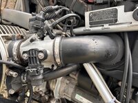
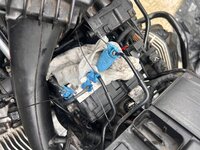
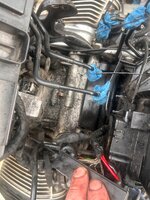
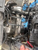
Had a look at my throttle body setup. It’s different to the 1150.

IMG_7327.jpeg


This chap used a pliers to remove the clip and look what he found 🙈 I’ll add an inspection in here to the list. I’m not loving the rubber gasket going from the throttle body to the cylinder head. If I go near that I’ll have to replace it so I’ll leave it be for now. Looking further, it seems only the outer bit is a bit crusty and it looks like quite a big part. I live in hope.

https://www.ukgser.com/community/threads/clean-your-throttle-body.222173/
 
Re AI's take on TB syncing.

It's all well.and goid saying nit to adjust the left s8de, leeping that as a baseline. Printing that in bold as though it is important is misleading. Depending on wear, the keft side canle may also need sone adjustment, that should be done first, to set the slack on that side. The top adjuster should also be considered, to make sure left and right are somewhere in the middle of their adjustment ranges.
The one comment that really should have been in bold italics is to not touch the throttle syop screws. These screws are set by the manufacturer ( not BMW) to ensure an exact airflow past the butterfly. The ECU 8s them programmed for that exact airflow, with the steppers toake small adjustments for changes in density etc.
If these are moved, you can send the body off to a company in Germany to have it correctly reset. It is not overly expensive but takes a while for delivery and return plus customs handling to/from the UK/EU.
In one service many years ago Coopers' then new tech-wizz had a play with mine, I spitted the paint seal was broken. It never ran right after that service, except at idle. Once I had seen the broken seal I sent bith bodues away for a reset. That cured the rough running at part throttle. Sonething nire than bloboif paint would have been a good idea .
 
Re AI's take on TB syncing.

It's all well.and goid saying nit to adjust the left s8de, leeping that as a baseline. Printing that in bold as though it is important is misleading. Depending on wear, the keft side canle may also need sone adjustment, that should be done first, to set the slack on that side. The top adjuster should also be considered, to make sure left and right are somewhere in the middle of their adjustment ranges.
The one comment that really should have been in bold italics is to not touch the throttle syop screws. These screws are set by the manufacturer ( not BMW) to ensure an exact airflow past the butterfly. The ECU 8s them programmed for that exact airflow, with the steppers toake small adjustments for changes in density etc.
If these are moved, you can send the body off to a company in Germany to have it correctly reset. It is not overly expensive but takes a while for delivery and return plus customs handling to/from the UK/EU.
In one service many years ago Coopers' then new tech-wizz had a play with mine, I spitted the paint seal was broken. It never ran right after that service, except at idle. Once I had seen the broken seal I sent bith bodues away for a reset. That cured the rough running at part throttle. Sonething nire than bloboif paint would have been a good idea .
Yeah the ai is interesting and frankly terrifying at the same time. Thanks for your comment, I didn’t knuw there is a top adjuster 😃 I assume it’s the one at the grip itself.
I learned my lesson about the screws before on a different bike. It may not seem it but I’m being very careful not to mess any thing up. Bike runs/ran quite well.

Plan is to do the throttle body sync at some point next week. Get the brakes sorted first.

My mum is sick. Dreadful chest infection. Bit worried about her so not visiting today. She says she might have Covid.

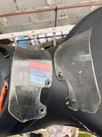
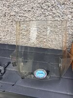
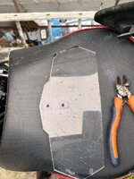
Instead I’ve taken an interest in the screen! It’s scrubbed up quite nicely. I might have a look in the hardware for something to shine it up a bit. Sends how hazy it is when it dries! Hairdryer to get the sticker off…

IMG_7331.jpeg
IMG_7332.jpegIMG_7333.jpegIMG_7334.jpeg


I’ve also come up with a theory that the distance a dropped nut / bolt / small part bounces is directly proportional to how tidy the shed is 😂😂
 
It’s going to fight me the whole way…
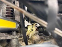
Released the right abs bolt biggie fo I get it out? The left is even more in accessible and I’ve mangled the fixing Not sure how to get that out wet other.

I read there are three bolts? Anyone any idea where the third is? Is it that pop rivet?
IMG_7339.jpeg
 

Attachments

  • IMG_7337.jpeg
    IMG_7337.jpeg
    355.2 KB · Views: 11
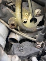
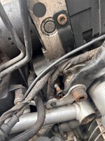
What a mess. The bolt on the left and the bolt in the center ftont have sheared off. Both horribly corroded. Managed to get the one on the right out.

Guess I’m going to have to drill out the center bolt and the one on the left. And what is with the pop rivit? I ‘ll do that last if I have to…

Now I need to find a really long has drill bit for that center one. What an unholy mess. Lot of brake fluid in here before many moons ago. Looking top down towards the bars, the brake line on the Left is different to the others. Starting to suspect someone has been in here before. With tough paws…IMG_7340.jpegIMG_7341.jpegIMG_7342.jpegIMG_7343.jpeg
 
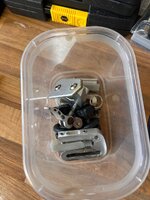
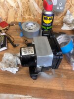
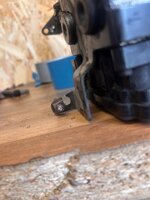
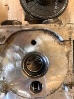
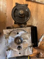
Ok I could use some guidance from anyone who has done this before. I cut the tangs off with a sharp chisel. Gently removed the motor. Did something fly across the room when I pulled the bearing out????

The two metal prongs that go into the abs modulator - they are very stiff. Should they be? It’s hard to push the bearing back on? Quitting now. Need advice and don’t want to annoy dr Farkoff

Yet

Oddly, I’m comfortable putting on bolts and a bar / bracket to hold the new pump in.

I guess the ford motor will have an identical bearing and spring etc which I can open inside a bin bag or something😏


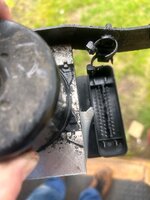
IMG_7357.jpeg


IMG_7356.jpegIMG_7355.jpeg


Back
Top Bottom