Speed sensor

Kenny Rodkiss

Well-known member
UKGSer Subscriber
Joined
Jan 6, 2002
Messages
1,154
Reaction score
21
Location
Scottish borders
2010 R1200GSA, NO abs.

Took a run up to Edinburgh the other day and noticed my speedo was reading very low, like 20mph when I was probably at 60.
It eventually went down to zero and stayed there with the occasional wave up to 10mph.
Having no speedo seemed to confuse the on board computer a bit.
Outside temp stuck at 13°.
Fuel gauge seemed to work fine but the other parameters were way off as I had lost the speed and distance input for calculations.
Once home I took out the sensor for a look.
It was clean as a clean thing.
Check the wiring and connector, looked all OK.
Refitted and speedo works but waving up and down and reading low.
New sensor fitted today and all is well again. 👍
Is there a way to check the old sensor to find out if it is the cable or the sensor?
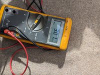
I can get a resistance reading with the positive probe on pin one and neg on pin two, but nothing if I reverse the connections.PXL_20230913_104852691.jpgPXL_20230913_105354593.jpg
 

Attachments

  • PXL_20230913_105031259.jpg
    PXL_20230913_105031259.jpg
    239.6 KB · Views: 17
I've just had to fork out for another one of these (the old one was an OEM replacement, it lasted only 2 years!).

Interested to test the old one, so I'd like to know if there's a way of testing it. I'm guessing it will need a (low) power supply and something to simulate the toothed wheel? Or would a multimeter be difficult power?

Sent from my SM-G975F using Tapatalk
the original sensor/cable has lasted 13 years.
Replacment was just over £100.
I believe there are two types of sensor, passive and active.
afaik the bmw one is an active sensor in that the ecu sends a reference voltage to the sensor and the sensor must alter it in someway to let the ecu know how fast things are turning.
I think you need an oscilloscope to be able read the sensors wave pattern.
I was just wondering if there was a simpler way of telling if it was the sensor or the cable at fault.
 
It's not a sensor, it's a pulse generator

Basically its coil with a magnet inside that generates a magnetic field. the holes in the reluctor ring , interrupts the field and create a pulse

the pulses are read by the computer / magic happens and electrons excite things and hey presto - speed is displayed

the magnetic field has probably diminished , so the pulses cannot be seen
That's useful. I mean, from the point of view trying to work out why it failed. Maybe the coil moulded into the plastic is somehow

The original had 10yrs before it failed...

Sent from my SM-G975F using Tapatalk
 
It's not a sensor, it's a pulse generator

Basically its coil with a magnet inside that generates a magnetic field. the holes in the reluctor ring , interrupts the field and create a pulse

the pulses are read by the computer / magic happens and electrons excite things and hey presto - speed is displayed

the magnetic field has probably diminished , so the pulses cannot be seen
If it was just a coil of wire, why can't I get a resistance reading in both directions with a multimeter?
I only get a reading with positive on pin 1 and negative on pin 2 at the connector.
If I reverse the connections I get no reading.
Maybe a diode in there somewhere?
 
Butchered the old one just for a look.
Two wires go into the sensor with two crimp connections to a chip on the side of a small magnet.
The other side of the chip has four metal fingers that go to another chip that sits on top of the magnet.
Definitely doesn't work now.PXL_20231105_151544084.MP.jpgPXL_20231105_151559169.jpg
 
Thanks for taking the time to dismantle and post, always interested in the internals of these potted units.
It would be nice to find out what the chip numbers are.
 
It's not a sensor, it's a pulse generator

Basically its coil with a magnet inside that generates a magnetic field. the holes in the reluctor ring , interrupts the field and create a pulse

the pulses are read by the computer / magic happens and electrons excite things and hey presto - speed is displayed

the magnetic field has probably diminished , so the pulses cannot be seen
Well that is really splitting hairs. Sure it generates pulses but for the purpose of sensing the wheel's rotational speed.

Sent from my SM-T813 using Tapatalk
 
Well that is really splitting hairs. Sure it generates pulses but for the purpose of sensing the wheel's rotational speed.

Sent from my SM-T813 using Tapatalk
No not splitting hairs, ask BMW what that part is called and the answer will be - Pulse generator

It's not a sensor, and it cant sense the wheels rotational speed

All that unit does is generate a pulse when the magnetic field it creates is interrupted - (that's what the chip at the end does)

it cant work out speed or rotation or how many pulses its generated, as it has no other functions on the chip

The ABS module counts the pulses and works out rotational speed and monitors against reference values , and it also sends the results to the Kombi in the way of a speed value

It gets the generic name "sensor" as its an easier concept for joe public to understand
I know what BMW calls it. I also know that BMW calls valve shims "oil sinks" so that really doesn't carry any weight with me. I also know the principle of operation.

There are a great many sensors in this world - temperature sensors, pressure sensors, vacuum sensors, motion sensors, light sensors, radiation sensors, etc. and ABS sensors. For the most part they do not "work out" the actual measurement of that which they are sensing but rather they provide an input to a circuit that converts the analog or digital signal from the sensor to some value.
 
It's not a sensor, it's a pulse generator

Basically its coil with a magnet inside that generates a magnetic field. the holes in the reluctor ring , interrupts the field and create a pulse

the pulses are read by the computer / magic happens and electrons excite things and hey presto - speed is displayed

the magnetic field has probably diminished , so the pulses cannot be seen
You need to read up on the difference between active and passive sensors as you have confused the two.

Sent from my SM-T813 using Tapatalk
 
You need to read up on the difference between active and passive sensors as you have confused the two.

Sent from my SM-T813 using Tapatalk
No not really, you seem to know it all, please enlighten me
 
No not really, you seem to know it all, please enlighten me
OK, with the assistance of MEVOTECH.....

You described the physical construction of a passive sensor which works like this:

Passive (Analogue/AC/Variable-Reluctance)
Passive sensors generate an induction signal, which may be represented by a sinusoidal wave form on an oscilloscope.
A passive sensor is located in close proximity to a “toothed” impulse or encoder ring; as part of the wheel hub or CV shaft. The sensor contains a coiled magnet which creates a magnetic effect, in relation to the encoder ring.
As the toothed encoder rotates, the magnetic field will change polarity creating an alternating voltage in the sensor coils; producing the sinusoidal waveform. The frequency and amplitude of this alternating voltage changes in direct relation to wheel speed. As wheel rotation increases, the larger the frequency and amplitude of the signal.
As passive sensors require somewhat substantial movement (rotation of the wheel) to read the generated signal (not enough amplitude), they are only “useful” above 4-5 MPH (6-8 KPH). For the most part, this disqualifies them for use with modern safety, comfort and driver assistance systems.
Additionally, as passive sensors depend on the magnetic field created by the sensor magnet and the encoder, the distance between the two is crucial. If the gap between the sensor and the encoder is out of specification, the ability to generate a correct signal may be impacted. Compounding this, the magnetic field may attract fine metallic particles from the road over time. These may accumulate on the sensor end and impair correct operation. If placed on a CV shaft, the encoder may also become damaged or worn from road debris. A missing or damaged tooth can lead to inconsistent signal output.


But then you described the output of an active sensor that works like this:

Active (Digital/DC/Magneto-Resistive)
When compared to passive sensors, active sensors have significantly improved low-speed performance and are able to read a signal up to when almost all vehicle motion has ceased. Moreover, the direction (forward or reverse) of wheel rotation can also be determined.
Active sensors are designed around a package of integrated electronics which are supplied voltage from the ABS module. There are a number of different versions of active sensor implementation but generally, a type of the encoder ring with alternating pole directions is located in the seal of the bearing on a hub assembly.
Similar to the passive sensor, as the ring rotates, the integrated electronics identify the alterations in the magnetic field. However, the electronics are able to convert this information into a digital output, which can be easily processed and utilized by vehicle safety, comfort and assistance systems. This signal may be represented by a square waveform on an oscilloscope.
Using aspects of Hall sensor design, active sensors are more precise and accurate, able to detect the smallest variations in the magnetic field and allow for a larger gap between sensor and ring, compared to passive sensors. As they do not rely on an external ring, active sensors are less prone to fluctuations in signal generation and interpretation due to environmental or road conditions.


The sensor mentioned by the OP is the latter type which explains the resistance readings.
 
Every day is a school day.

I had wrongly assumed that with them being a 2 wire sensor they were passive sensors. This would explain why I could not get an output to the scope when testing a sensor that I thought to be good.
The only active sensors that I have used have been 3 wire. +ve , -ve and signal, although my experience is limited.

Would it be possible to check the square wave from these sensors by having them connected in circuit and effectively back pinning the sockets. ( making up a test lead with compatible plugs and sockets to T off ).
Any idea of the amplitude of the square wave from these sensors.?
I am guessing at it being a 5v circuit but, !!! ???????
 
IC chip can function as an amplifier, oscillator, timer, counter, logic gate, computer memory, microcontroller or microprocessor.... creates a signal so the ECU actually notices - the reality - its a nicer way to get a more expensive failure mode...

anyone notice ALL UK vehicles made in germany take parts on the production line from the faulty parts bin, german ones use the good parts bin and russian built toyota's from the never ever go wrong parts bin !
 
Last edited:
Butchered the old one just for a look.
Two wires go into the sensor with two crimp connections to a chip on the side of a small magnet.
The other side of the chip has four metal fingers that go to another chip that sits on top of the magnet.
Definitely doesn't work now.View attachment 290914View attachment 290915
Interesting! I have another duff one here if you want another go, yunno, so you can get it all really neat

Kidding aside, you've answered a question for me > what the hell is in there!


Sent from my SM-S908B using Tapatalk
 
By way of a small update on this and my own experience.

After getting my wallet out recently to replace the 20 month old speed sensor, I've noticed a difference - that I wasn't expecting.

With the new sensor fitted, it is immediately apparent that the triangle/brake warning disappears really quickly. I'm sure even the original didn't respond so quickly. The original was at least 7 years old - but I'm guessing it was the item shipped with the bike at new.

So here's hoping this one lasts more than 20 months . It's a lot of money for what it is...

Sent from my SM-S908B using Tapatalk


Back
Top Bottom